Erasing an EPROM with Alternative Devices

I’ve come into possession of an EPROM and got a programmer for it. Writing data to it was easy. Erasing data is another matter. Note that I said EPROM and not EEPROM. What’s the difference? An The first E in EEPROM means “Electrically.” And Electrically Erasable Read Only Memory can be cleared by using some electric circuit. The EPROM I have must be erased through UV light. There is a window on the ceramic package that exposes the silicon underneath. With enough UV light through this window, this chip should be erased.

There are devices sold to specifically erase such memory. I’m not using those. Instead, I have a number of other UV sources to test with. These are

  • The Sun
  • A portable UV phone Cleaner
  • A Clamshell UV Phone Cleaner
  • A Tube Blacklight

I’m using a M27C256 32k EPROM. To know whether my attempt at erasing worked or not I needed to first put something on it. I filled the memory with binary digits counting from 0 to 255, repeating the sequence when I reached the end. The entire 32K was filled with this pattern. To produce a file with the pattern I wrote a few lines of code.

// See https://aka.ms/new-console-template for more information
byte[] buffer = new byte[0x7FFF];
for(int i = 0;i <buffer.Length;i++)
{
    buffer[i] = (byte)i;
}
using (FileStream fs = new FileStream("content.bin", FileMode.Create, FileAccess.Write))
{
    fs.Write(buffer, 0, buffer. Length);
}

Now to get the resultant file copied to the EPROM. The easiest way to do that is with a dedicated EPROM programmer. They are relatively cheap, easy to find, and versatile. I found one on Amazon that worked well for me. Using it was only a matter of selecting what type of EPROM I was using, selecting a file containing the content to be written, and selectin the program button.

The software for writing information to the EPROMs

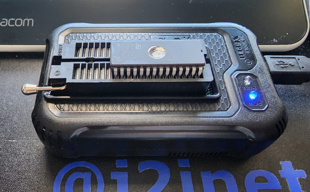
Reading from the EPROM is just as simple. After the EPROM is connected to the programmer and the EPROM model is selected in the software, it provides a READ button that copies all the bytes from the memory device and displays them in the hex editor. To determine whether the EPROM had been erased I will use this functionality. Now that I have a way to read and write from the EPROM, let’s test the different means of erasure.

Using the Sun

These results were the most disappointing. After having an EPROM out for most of the day, the ROM was not erased. Speaking to someone else, I was told that it would take several days of exposure to erase the EPROM. I chose not to leave the EPROM out for this long, as I’d risk forgetting it was out there when the weather becomes more wet.

Using a Portable UV Sanitizer

The portable UV Sanitizer that I tried was received as a Christmas gift at the end of 2022. Such devices are widely available now in the wake of COVID. This unit charges with a USB cable and runs off of a battery. When turned on, it stays on until it is either turned off, the battery goes dead, or someone turns it over. This unit will only emit light when the light is facing downward. I speculate this is a safety feature; you won’t want to look directly into the EV light.

My first attempts to erase one of the EPROMs with this sanitizer were not successful. After several sessions, the EPROMs still had their data on them. While I wouldn’t look directly into the UV light I could point my camera at it safely. The picture was informative. The light had a brighter level on the end that was closer to the power source, and was very dim at the end. Before, I was only ensuring the window of the EPROM were under some portion of the lighting tube. Now, I knew to ensure it was close to the brighter end of the UV emitter. Using the new placement, I was able to erase an EPROM in about 60 minutes.

UV Sanitizer with the EPROM at the brighter end.

Provided that someone is only erasing a single EPROM and isn’t in a hurry, I think that this could make for an adequate solution for erasing an EPROM. If there’s more than one though his might not work as well, especially when one considers the time needed to recharge the battery after it has been diminished by an erasing session.

Clamshell UV Phone Cleaner

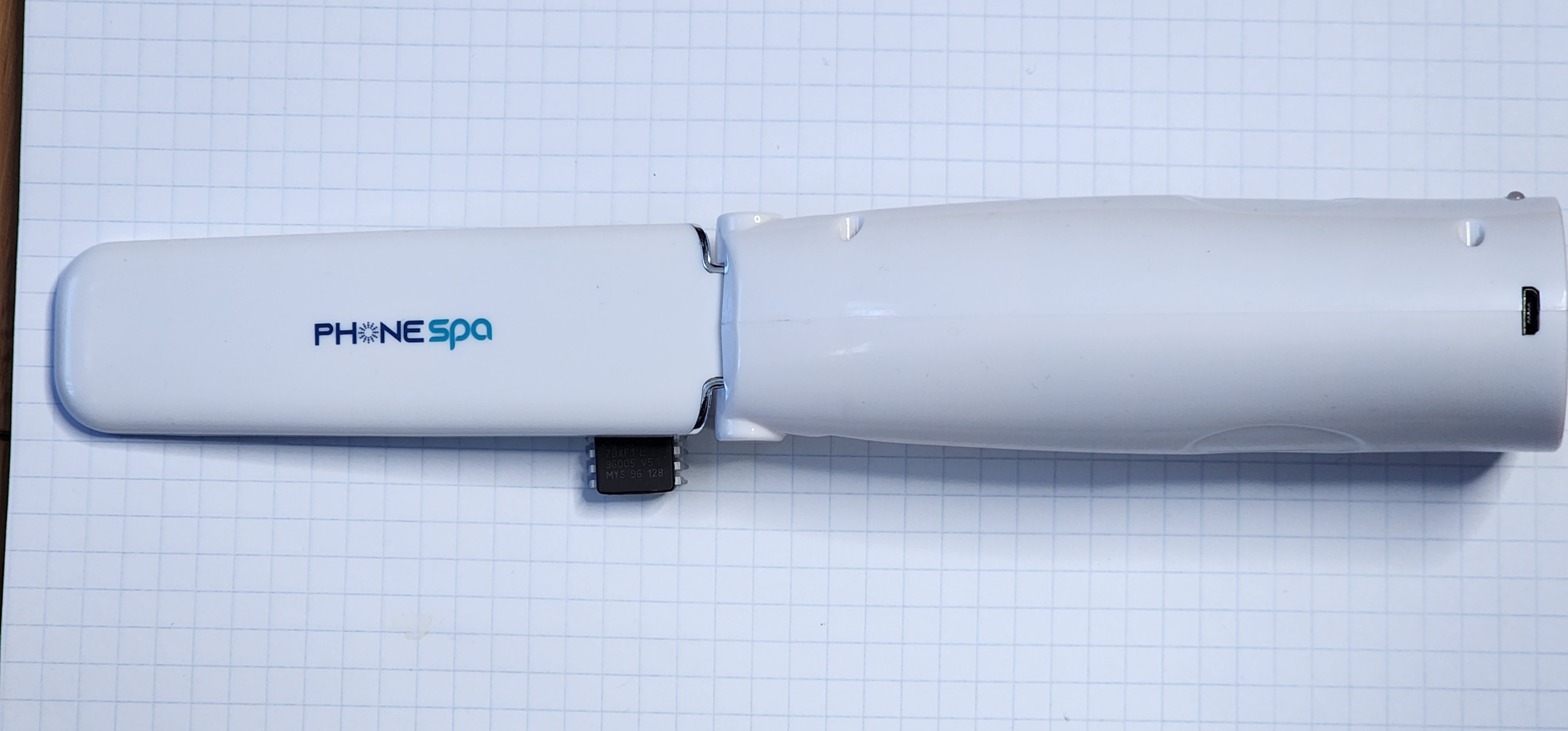
I received this clamshell UV phone cleaner as a gift nearly a decade ago. This specific model isn’t sold any more, but newer variations are available under the description PhoneSoap. These have a few advantages over the portable UV sanitizer. It runs from a 12 volt power source. There’s no waiting for it to recharge before you can use it. It also appears to be a lot brighter. The UV emitter automatically deactivates when the case is being opened, but there is a brief moment where the case is just being opened but the light hasn’t turned off yet in which some of the light spills out of the unit. It is either a lot brighter, or it has more light in the visible spectrum. The unit I use has emitters on both the hinged and the lower area of the case. EPROMs placed in it could be oriented face-up or face-down and still be erased. When this case is closed, the emitter turns on for 300 seconds and then turns off. I’d like for it to be longer for my purposes, but 300 seconds isn’t bad. After I let an EPROM sit for one 5-minute session in the sanitizer, it still has data on it. But after a second 5-minute session it showed as erased. I think this unit is worthy of consideration.

Tube UV Light

I have an old UV tube light that I purchased in my teens. I dug it up and found a power supply for it. The light still works, but after leaving an EPROM in direct contact with it for well over 24 hours I found no change. I speculated that this would be the outcome for a few reasons. Among which is that UV lights of this type are commonly where people can see them. The cleaning UV lights have warnings to keep them away from skin and eyes. From the glimpse that I got of them through the phone’s camera, it looks that they are working in a different wavelength. Not that this is a true measure of the true bandwidth. But there’s not much to be said about the tube light.

The Winner

The clear winner here is the clamshell UV light. It was easy to use and was able to erase the EPROM in ten minutes. The portable UV cleaner comes in second. The other sources didn’t cross the finish line given a generous amount of time to do so. It might be possible to eventually erase an EPROM with them, but I don’t think it is worth the time.

Now that I have a reliable way to erase these EPROMs, I can use these in the MC6800 Computer that I was working on.


Mastodon: @j2inet@masto.ai
Instagram: @j2inet
Facebook: @j2inet
YouTube: @j2inet
Telegram: j2inet
Twitter: @j2inet

Posts may contain products with affiliate links. When you make purchases using these links, we receive a small commission at no extra cost to you. Thank you for your support.

Jameco Valuepro BB-4T7D 3220-Point Solderless Breadboard

The File System Watcher::Reloading Content Automatically

I was performing enhancements on a video player that read its content at startup, and then would serve from that content on demand. The content, though loaded from the file system, was being put in place by another process. Since the primary application only scanned for content at startup, it would not detect the new content until after the scheduled daily reboot.

The application needed a different behaviour. It needed to detect when content was updated and rescan content accordingly. There are several ways that this could be done, with the application occasionally scanning its content being among the most obvious solutions. There are better solutions. The one I am sharing here is the File System Watcher. I’ll be looking at using the implementations for NodeJS and .NET.

The File System Watchers keeps track of files in specific paths and notifies an application when a change of interest occurs. Once could watch an entire folder or watch only specific files. If any files change, the application receives a notification.

Let’s consider how this feature is used in NodeJS first. You’ll need to import the file system object. The file system object has a function named watch that accepts a file path. The object that is returned is used to received notifications when an item within that path is created or updated.

const fs = require('fs')
const readline = require('readline');
const path = require('path');

var watcher;
let watchPath = path.join(__dirname, 'config');
console.log(`Watch path: ${watchPath}`);
watcher = fs.watch(watchPath)
watcher.on('change', (event, filename)=> {
	console.log(event);
	console.log(filename);
});

console.log('asset watcher activated');

When a configuration file is change, how that is handled depends on the logic of how your application works.

In the .Net environment there’s a class named FileSystemWatcher that accepts a directory name and a file filter. The file filter is the pattern for the file names that you won’t considered. Use *.* to monitor for any file. You can also filter for notifications of the file attributes changing. Instances of FileSystemWatcher exposes several events for different types of file system events.

  • Renamed
  • Deleted
  • Changed
  • Created

When an event occurs, the application receives a FileSystemEventArgs object. It provides three properties about the change that has occurred.

  • ChangeType – Type of event that occurred
  • FullPath – The full path to the file system object affected
  • Name – the name of the file system object affected

These should tell you most of the information that you need to know the nature of the change.

Whether in NodeJS or .Net, using the file system watcher provides a simple and efficient method for detecting when vital files have been updated. If you decide to add features to your application to ensure it is responsive to changes in files, you’ll want to use it in your solutions.

Find the source code for sample apps here

https://github.com/j2inet/FileSystemWatcherDemo

.Net Sample App

The .Net Sample App monitors the executable directory for the files content.txt and title.txt. The application has a title area and a content area. If the contents of the files are changed, the application UI updates accordingly. I made this a WPF app because the binding features makes it especially easy to present the value of a variable with minimal custom code. I did make use of some custom base classes to keep the app-specific code simple.

using System;
using System.Collections.Generic;
using System.DirectoryServices;
using System.IO;
using System.Linq;
using System.Security.Policy;
using System.Text;
using System.Threading.Tasks;

namespace FileSystemWatcherSample.ViewModels
{
    public  class MainViewModel: ViewModelBase
    {
        public MainViewModel() {
            var assemblyFile = new FileInfo(this.GetType().Assembly.Modules.FirstOrDefault().FullyQualifiedName);
            var parentDirectory = assemblyFile.Directory;
            Directory.SetCurrentDirectory(parentDirectory.FullName);

            FileSystemWatcher fsw = new FileSystemWatcher(parentDirectory.FullName);
            fsw.Filter = "*.txt";
            fsw.Created += FswCreatedOrChanged;
            fsw.Changed += FswCreatedOrChanged;
            fsw.NotifyFilter = NotifyFilters.CreationTime | NotifyFilters.LastWrite | NotifyFilters.FileName;
            fsw.EnableRaisingEvents = true;
        }


        void FswCreatedOrChanged(object sender, FileSystemEventArgs e)
        {
            var name = e.Name.ToLower();
            switch (name)
            {
                case "contents.txt":
                    try
                    {
                        Content = File.ReadAllText(e.FullPath);
                    }catch(IOException exc)
                    {
                        Content = "<unreadable>";
                    }
                    break;
                case "title.txt":
                    try
                    {
                        Title = File.ReadAllText(e.FullPath);
                    } catch(IOException exc)
                    {
                        Title = "<unreadable>";
                    }
                    break;
                default:
                    break;
            }
        }

        private string _title = "<<empty>>";
        public string Title
        {
            get => _title;
            set => SetValueIfChanged(() => Title, () => _title, value);
        }

        string _content = "<<empty>>";
        public string Content
        {
            get => _content;
            set => SetValueIfChanged(()=>Content, ()=>_content, value);
        }
    }
}

Node Sample App

The Node Sample App runs from the console. In operation, it is much more simple than the .Net application. When a file is updated it prints a notification to the screen.

const fs = require('fs')
const readline = require('readline');
const path = require('path');


function promptUser(query) {
    const rl = readline.createInterface({
        input: process.stdin,
        output: process.stdout,
    });

    return new Promise(resolve => rl.question(query, ans => {
        rl.close();
        resolve(ans);
    }))
}


var watcher;
let watchPath = path.join(__dirname, 'config');
console.log(watchPath);
watcher = fs.watch(watchPath)
watcher.on('change', (event, fileName)=> {
    console.log(event);
    console.log(fileName);
    if(fileName == 'asset-config.js') {
      targetWindow.webContents.send('ASSET_UPDATE', fileName);
    }
  })
  console.log('asset watcher activated');


var result = promptUser("press [Enter] to terminate program.")

Retro: Building a Motorola 6800 Computer Part 1

I was cleaning out a room and I came across a box of digital components. Among these components were a few ICs for microcontrollers and microprocessors. Seeing these caused me to revisit interest that I had in computer hardware during a time prior to me deciding on the path of a Software Engineer. I decided to make a simple, yet functional computer with one of the processors. I selected the Motorola 6808 from what was available. There was a more capable Motorola 68K among the ICs, but I decided on the 6808 since it would require less external components and would be a great starting point for building something. It could make for a great teaching aid for understanding some computer fundamentals.

MC6800 Series Hello World on YouTube

Hello World

The first thing I want to do with it is simple. I just want to get the processor in a state where it can run without halting. This will be my Hello World program equivalent. Often times with Hello World programs, the goal is simply to produce something that compiles runs without failing, and performs some observable action. Hello World programs validate that one’s build system is properly configured to begin producing something. The program itself is trivial.

About the 6800

This processor family is from before my time, initially made in 1974. The MC6800 series of processors comes in a few variants. They differ on their amount of internal ram, stand-by capabilities, and clock speed. These are small variations. I’m using the MC6808, but will refer to it as a 6800 since most of what I write here is applicable to all of these processors. This 8-bit processor has only a few registers to track, a 16-bit address line, and a few control lines. List any processor, it has a program counter and stack pointer. It also has an index register, and a couple of 8-bit accumulators. The Index, stack, and program counters are all 16-bit while the two accumulators are 8-bit.

The processor only natively performs integer math operations. But there is a library for floating point operations. In times past it had been distributed as an 8K ROM. But the source code for this library is readily available and could be place on someone’s own ROM. You can find the source code on GitHub.

MC6800 Block Diagram Image Credit: Wikipedia.org

Instruction Set

This processor has an instruction set of only 72 instructions. The instructions + operands range with a usual size of between 1 to 3 bytes. At this size and simplicity, even putting together a simple program without an assembler could be done. Many instructions are variations on the same high-level operation with a different addressing mode. For my task goal, I don’t need to get deep into understanding of the instruction. I just needed to know what is a 1 byte operation that I could do without any additional hardware or memory needed. Many processors support an instruction often called nop, standing for “No Operation.” This instruction, as its name suggest, does nothing beyond take up space. My plan was to hard-wire this instruction into the system. This would let it run without any RAM and without causing any faults or halting conditions.

For this processor, the numerical value for the nop instruction is 0x01. This is an easy encoding to remember. To wire this instruction in the circuit, I only need to connect the least significant bit of the processor’s data line to a high signal and tie the other ones to a low signal.

Detecting Activity

It is easy to think of a processor that is only executing nop instructions as doing nothing at all. This isn’t the case though. The processor is still incrementing its program bus. As it does, it is asserting the new address over the processor’s address lines to specify the next instruction that it is trying to fetch. Some output status lines will also indicate activity. The R/!W line will indicate read operations, the BA (Bus Address) line will be high when ever the processor isn’t halted, ant the VMA line will be high when the processor is trying to asset an address on the address bus. The processor also responds to some input lines. There are three input lines that have an effect on the processor when they are in the low state. RESET, HALT, and IRQ all effect execution. I’ll need to ensure those are tied low. Most important of all, the processor needs to receive a clock signal within an acceptable range. The clock signal is necessary for the processor to coordinate it’s actions . If the clock signal is too high or too low, then the process might not function correctly. That said, I’m going to intentionally try to run the processor at a rate that is lower than what is on the spec sheet for reasons to be discussed.

As the processor is running, I should be able to monitor what’s going on by monitoring a few lines, especially on the address line. If I connect light emitting diodes (LEDs) to the address lines then I should observe whether each connection is in a high or low state by seeing which LEDs are on or off. But with the processor running at a clock speed of 1MHz – 2MHz, the processor could go through its entire address space at a rate faster than I can perceive. If I run the clock at a reduced speed, then I might make the processor progress slow enough so that I can watch the address lines increment. To achieve this, I’m going to make a clock circuit and put the output through a counter IC. If you are familiar with digital counting circuits, you know that each binary digit will be changing at half the speed of the digit before it. I can use the output of the circuit to get the clock running at 1/2, 1/4, 1/8,…,1/256. I can get the clock into the kilohertz range, which would be slow enough to see the address lines increment.

The Circuit

For the clock circuit, I have a 4MHz crystal wired into a circuit with some inverters, resisters, and capacitors. I take the output of that and pass it through another inverter before passing it on to the processor (or the counter between the processor and clock).

For the processor, most of the work is connecting LEDs with resistors to limit the current. Additionally I’ve for the instruction 1 wired to the data bus. With this wired, the only thing the system needs is power.

The Outcome

I’m happy to say that this worked. The processor started running and I can see the address bus values increasing through the LEDs on the most significant bits.

Next Steps

Now that I have the processor in a working state, I want to replace the hard-wired instruction with an EPROM and add RAM. Once I’m confident that all is well with the EPROM and RAM then I’ll add some interfaces for the outside world. While the parts that I think that I’ll need are generally out of production (though there are some derivative processors still available new) used versions are available for only a few dollars. Overall though this is a temporary diversion. Once it is developed to a certain point, it will be shelved, but that’s not the end of my hardware exploration. There are some things I’d like to do with some ARMs processors (likely an STMF32 arm processor). Many of the ARMs processors I’ve looked at are fairly complete system-on-a-chip components and don’t require a lot of hardware to get them to their minimal working state beyond a clean power supply.

Resources

One of the nice things about dabbling in Retro Computing is that there are plenty of sources available for the hardware. If you find this interesting and want to try some things out yourself, here are some resources that may be helpful.


Mastodon: @j2inet@masto.ai
Instagram: @j2inet
Facebook: @j2inet
YouTube: @j2inet
Telegram: j2inet
Twitter: @j2inet

Posts may contain products with affiliate links. When you make purchases using these links, we receive a small commission at no extra cost to you. Thank you for your support.