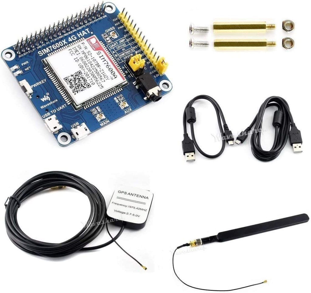
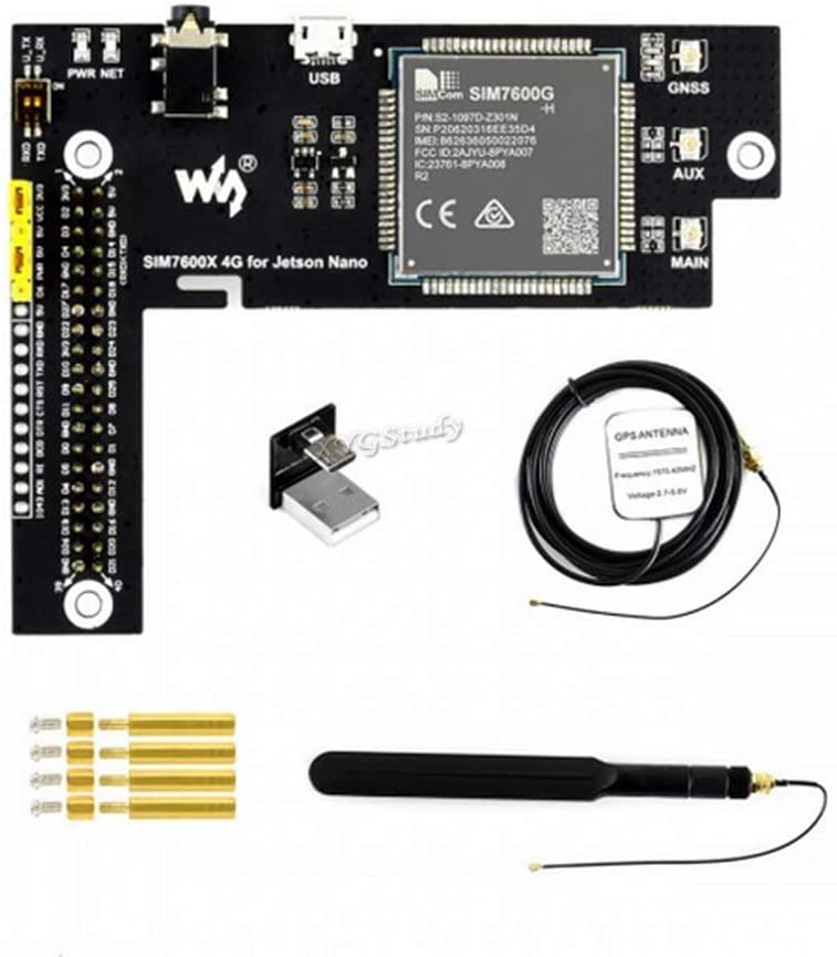
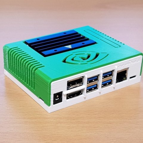
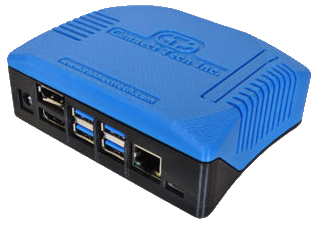
I’ve been using the Waveshare 7600 4G for the Jetson Nano (hereon referred to simply as the 7600). It gives the Jetson a connection for 4G mobile networks, GPS, and the ability to make and receive phone calls and SMS. (If you are looking for information on getting a WiFi connection see this post.) The Waveshare 7600 4G is a board built around the SIMCOM SIM7600X, an integrated circuit for providing communications functionality for a mobile phone. Waveshare makes variations of this device for both the Raspberry Pi and the Jetson Nano. While there is a wide amount of overlap in the usage of both devices, there are differences that are not immediately apparent from the top-level documentation. That said, reading documentation on one gives insight in using the other. The pin assignments used differ, but most of usage and functionality are the same.
When I initially looked at the Waveshare 7600 4G for the Jetson, there were elements of usage that didn’t make sense to me without consulting documentation from the chip maker and the schematic provided by Waveshare.

You don’t need to be familiar with the electrical schematic for the Waveshare board to use it. But if you would like more insight as to what the board is doing, continue reading.

A quick glance of the pinout for the SIMCOM 7600 integrated circuit gives hints at a number of interfaces the chip supports. There are pins for power control, USB data transfer, interfacing to an SD card, GNSS, Flight mode, I2C, a UART interface, functionality concerning batteries, and analog to digital conversion. While the SIMCOM 7600 supports all of these interfaces, the Waveshare 7600 board built around this supports a subset of these interfaces; some of the lines on the SIMCOM 7600 are not connected to an external interface.
The schmatic that Waveshare provides is available on their Wiki at this URL. In the center of the schematic is the SIM7600.

Looking at this part of the diagram alone, you might notice that the pins labeled SCL and SDA are both tied to the positive voltage source instead of to other circuitry. These labels are associated with an I2C interface. Since the Waveshare’s board does not bridge the I2C pins between the Jetson Nano and the SIMCOM 760X, there is no I2C that you can use. Let’s take a look at how Waveshare’s device is connected to the Jetson Nano’s 40 pin header.
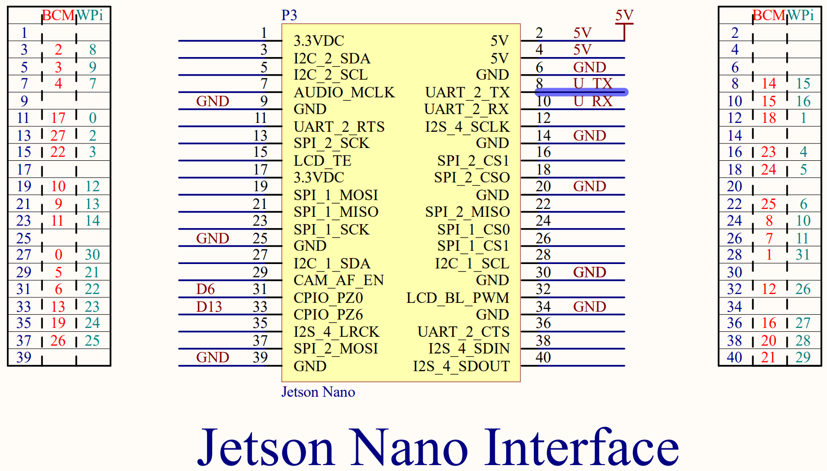
Here you can see that the Waveshare board connects to some voltage and ground lines on the 40-pin interface. The only pins related to functionality used are pins 8 and 10 on the Jetson, which connect the Jetson’s UART to the SIMCOM 7600’s UART, and pins 31 and 33 on the Jetson, which connect to pins labeled D6 and D13 on the Waveshare board. Let’s trace these lines.
The two UART lines don’t connect directly to the SIMCOM 7600X. Instead they pass through a pair of switches and an integrated circuit identified as TXB0108EPWR. According to a datasheet (PDF), this circuit is a level shifter.

This circuit isn’t providing any additional signals. It allows the SIMCOM 7600, which uses 1.8 volt signaling, to communicate with the Jetson Nano over 3.3 volt signaling. The two switches allow the SIMCOM 7600’s UART and Jetson’s UART to be disconnected from each other. It is also possible to connect directly to the 3.3volt side of this circuit through pins exposed on the board.

There’s a schematic for the USB port. There’s nothing significant in the USB connection that you need to know. When I first got my hands on this board I was wondering why there were interfaces for both USB and a UART. Why are there two connections? This was answered by reading the SIMCOM 7600 documentation. The 7600 can accept AT commands over either interface and perform data transfers over either interface. The USB port is set to suspend if it is not used within some time period. It becomes active again during certain wake events.
In the Waveshare Wiki, developers are instructed to set a pin of the Jetson Nano to high and then low to ensure that the Wavesare device is turned on. The following is a script that can Waveshare provides for doing this.
echo 200 > /sys/class/gpio/export
echo out > /sys/class/gpio200/direction
echo 1 > /sys/class/gpio200/value
echo 0 > /sys/class/gpio200/value
There is not an explanation given as to what this is doing. GPIO200 is connected to pin 31 on the Jetson’s 40 pin header. Pin 31 leads to a pin labeled D6 on the board. What does pin D6 do? On the schematic we find that D6 terminates on a jumper.

Layouts on an electrical schematic don’t necessarily map spatially. Looking at the physical connector in question, we can see more of what it does.

There is a jumper that can either bridge D6 to PWR, or bridge the 5V supply to power. In the above since PWR and 5V are connected, the PWR line will always be highm and pin 31 on the Jetson Nano is free for other purposes. If D6 and PWR are bridged, then the Jetson controls the power state of the board. The SIMCOM 7600 could go to a lower power mode for a number of reasons. This could include receiving a command instructing the SIMCOM 7600 to go to a lower power state. Pulsing this line will wake the SIMCOM 7600 up. If we look a little deeper at the schematic, we find PWR does not go directly to the SIMCOM 7600. It passes through another circuit.
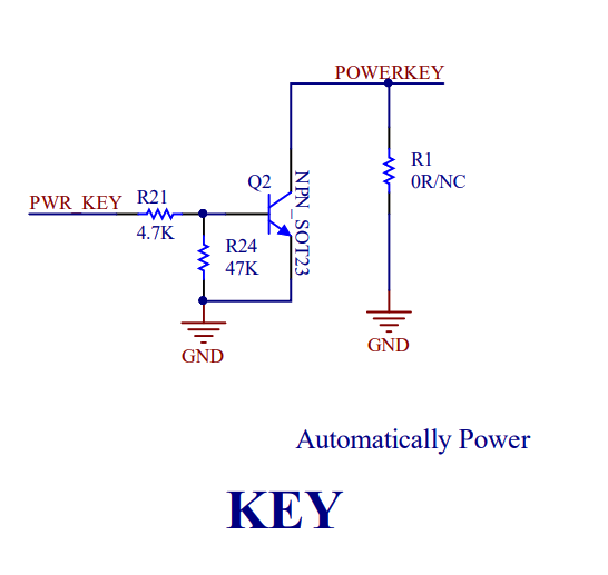
The end of the circuit labeled POWERKEY is connected to the SIMCOM 7600’s line of the same label. According to the SIMCOM 7600 documentation, connecting the power line to ground will power the unit on. (the POWERKEY line is connected to positive 1.8V internally within the SIMCOM 7600). The end result of this circuit could almost be viewed as being like an inverter; the high voltage from D6 or PWR results in the POWERKEY pin connecting to ground (low signal) and powering on. Sending a low signal to PWR causes the POWERKEY to be driven high by it’s internal resistor, which powers the SIMCOM 7600X off.
There is a circuit labeled “Flight Mode” that does something similar. The Flight Mode circuit bridges Pin 33 from the Jetson Nano to a pin on the SIMCOM 7600X labeled “Flight Mode.” As you may have inferred from using a phone, activating Flight Mode disables the radios within the SIMCOM 7600X.

There are a few other components on the schematic that don’t involve any signaling with the Jetson Nano. Of course, there is also the circuit that connects to the SIM card. Waveshare has also supplied a circuit for interfacing with earphones and a microphone. To use this feature you only need to connect a headset to the jack on the board.
There are three more interfaces on the schematic for the antennas. Two of these antennas are self-explanatory. The GNSS connector for a GPS antenna. The Main connector for a cellular antenna. There is a third antenna that is labeled as AUX on the Waveshare board, and DIV Ant on the schematic. While not strictly necessary, connecting an antenna to this connector can enhance the 4G performance of the SIM 7600.
That covers all of the circuits that connect to the Waveshare 7600X 4G.
See other posts on the NVIDIA Jetson.
Twitter: @j2inet
Instagram: @j2inet
Facebook: j2inet
YouTube: j2inet
Telegram: @j2inet
Posts may contain products with affiliate links. When you make purchases using these links, we receive a small commission at no extra cost to you. Thank you for your support.