Erasing an EPROM with Alternative Devices

I’ve come into possession of an EPROM and got a programmer for it. Writing data to it was easy. Erasing data is another matter. Note that I said EPROM and not EEPROM. What’s the difference? An The first E in EEPROM means “Electrically.” And Electrically Erasable Read Only Memory can be cleared by using some electric circuit. The EPROM I have must be erased through UV light. There is a window on the ceramic package that exposes the silicon underneath. With enough UV light through this window, this chip should be erased.

There are devices sold to specifically erase such memory. I’m not using those. Instead, I have a number of other UV sources to test with. These are

  • The Sun
  • A portable UV phone Cleaner
  • A Clamshell UV Phone Cleaner
  • A Tube Blacklight

I’m using a M27C256 32k EPROM. To know whether my attempt at erasing worked or not I needed to first put something on it. I filled the memory with binary digits counting from 0 to 255, repeating the sequence when I reached the end. The entire 32K was filled with this pattern. To produce a file with the pattern I wrote a few lines of code.

// See https://aka.ms/new-console-template for more information
byte[] buffer = new byte[0x7FFF];
for(int i = 0;i <buffer.Length;i++)
{
    buffer[i] = (byte)i;
}
using (FileStream fs = new FileStream("content.bin", FileMode.Create, FileAccess.Write))
{
    fs.Write(buffer, 0, buffer. Length);
}

Now to get the resultant file copied to the EPROM. The easiest way to do that is with a dedicated EPROM programmer. They are relatively cheap, easy to find, and versatile. I found one on Amazon that worked well for me. Using it was only a matter of selecting what type of EPROM I was using, selecting a file containing the content to be written, and selectin the program button.

The software for writing information to the EPROMs

Reading from the EPROM is just as simple. After the EPROM is connected to the programmer and the EPROM model is selected in the software, it provides a READ button that copies all the bytes from the memory device and displays them in the hex editor. To determine whether the EPROM had been erased I will use this functionality. Now that I have a way to read and write from the EPROM, let’s test the different means of erasure.

Using the Sun

These results were the most disappointing. After having an EPROM out for most of the day, the ROM was not erased. Speaking to someone else, I was told that it would take several days of exposure to erase the EPROM. I chose not to leave the EPROM out for this long, as I’d risk forgetting it was out there when the weather becomes more wet.

Using a Portable UV Sanitizer

The portable UV Sanitizer that I tried was received as a Christmas gift at the end of 2022. Such devices are widely available now in the wake of COVID. This unit charges with a USB cable and runs off of a battery. When turned on, it stays on until it is either turned off, the battery goes dead, or someone turns it over. This unit will only emit light when the light is facing downward. I speculate this is a safety feature; you won’t want to look directly into the EV light.

My first attempts to erase one of the EPROMs with this sanitizer were not successful. After several sessions, the EPROMs still had their data on them. While I wouldn’t look directly into the UV light I could point my camera at it safely. The picture was informative. The light had a brighter level on the end that was closer to the power source, and was very dim at the end. Before, I was only ensuring the window of the EPROM were under some portion of the lighting tube. Now, I knew to ensure it was close to the brighter end of the UV emitter. Using the new placement, I was able to erase an EPROM in about 60 minutes.

UV Sanitizer with the EPROM at the brighter end.

Provided that someone is only erasing a single EPROM and isn’t in a hurry, I think that this could make for an adequate solution for erasing an EPROM. If there’s more than one though his might not work as well, especially when one considers the time needed to recharge the battery after it has been diminished by an erasing session.

Clamshell UV Phone Cleaner

I received this clamshell UV phone cleaner as a gift nearly a decade ago. This specific model isn’t sold any more, but newer variations are available under the description PhoneSoap. These have a few advantages over the portable UV sanitizer. It runs from a 12 volt power source. There’s no waiting for it to recharge before you can use it. It also appears to be a lot brighter. The UV emitter automatically deactivates when the case is being opened, but there is a brief moment where the case is just being opened but the light hasn’t turned off yet in which some of the light spills out of the unit. It is either a lot brighter, or it has more light in the visible spectrum. The unit I use has emitters on both the hinged and the lower area of the case. EPROMs placed in it could be oriented face-up or face-down and still be erased. When this case is closed, the emitter turns on for 300 seconds and then turns off. I’d like for it to be longer for my purposes, but 300 seconds isn’t bad. After I let an EPROM sit for one 5-minute session in the sanitizer, it still has data on it. But after a second 5-minute session it showed as erased. I think this unit is worthy of consideration.

Tube UV Light

I have an old UV tube light that I purchased in my teens. I dug it up and found a power supply for it. The light still works, but after leaving an EPROM in direct contact with it for well over 24 hours I found no change. I speculated that this would be the outcome for a few reasons. Among which is that UV lights of this type are commonly where people can see them. The cleaning UV lights have warnings to keep them away from skin and eyes. From the glimpse that I got of them through the phone’s camera, it looks that they are working in a different wavelength. Not that this is a true measure of the true bandwidth. But there’s not much to be said about the tube light.

The Winner

The clear winner here is the clamshell UV light. It was easy to use and was able to erase the EPROM in ten minutes. The portable UV cleaner comes in second. The other sources didn’t cross the finish line given a generous amount of time to do so. It might be possible to eventually erase an EPROM with them, but I don’t think it is worth the time.

Now that I have a reliable way to erase these EPROMs, I can use these in the MC6800 Computer that I was working on.


Mastodon: @j2inet@masto.ai
Instagram: @j2inet
Facebook: @j2inet
YouTube: @j2inet
Telegram: j2inet
Twitter: @j2inet

Posts may contain products with affiliate links. When you make purchases using these links, we receive a small commission at no extra cost to you. Thank you for your support.

Jameco Valuepro BB-4T7D 3220-Point Solderless Breadboard

Retro: Building a Motorola 6800 Computer Part 1

I was cleaning out a room and I came across a box of digital components. Among these components were a few ICs for microcontrollers and microprocessors. Seeing these caused me to revisit interest that I had in computer hardware during a time prior to me deciding on the path of a Software Engineer. I decided to make a simple, yet functional computer with one of the processors. I selected the Motorola 6808 from what was available. There was a more capable Motorola 68K among the ICs, but I decided on the 6808 since it would require less external components and would be a great starting point for building something. It could make for a great teaching aid for understanding some computer fundamentals.

MC6800 Series Hello World on YouTube

Hello World

The first thing I want to do with it is simple. I just want to get the processor in a state where it can run without halting. This will be my Hello World program equivalent. Often times with Hello World programs, the goal is simply to produce something that compiles runs without failing, and performs some observable action. Hello World programs validate that one’s build system is properly configured to begin producing something. The program itself is trivial.

About the 6800

This processor family is from before my time, initially made in 1974. The MC6800 series of processors comes in a few variants. They differ on their amount of internal ram, stand-by capabilities, and clock speed. These are small variations. I’m using the MC6808, but will refer to it as a 6800 since most of what I write here is applicable to all of these processors. This 8-bit processor has only a few registers to track, a 16-bit address line, and a few control lines. List any processor, it has a program counter and stack pointer. It also has an index register, and a couple of 8-bit accumulators. The Index, stack, and program counters are all 16-bit while the two accumulators are 8-bit.

The processor only natively performs integer math operations. But there is a library for floating point operations. In times past it had been distributed as an 8K ROM. But the source code for this library is readily available and could be place on someone’s own ROM. You can find the source code on GitHub.

MC6800 Block Diagram Image Credit: Wikipedia.org

Instruction Set

This processor has an instruction set of only 72 instructions. The instructions + operands range with a usual size of between 1 to 3 bytes. At this size and simplicity, even putting together a simple program without an assembler could be done. Many instructions are variations on the same high-level operation with a different addressing mode. For my task goal, I don’t need to get deep into understanding of the instruction. I just needed to know what is a 1 byte operation that I could do without any additional hardware or memory needed. Many processors support an instruction often called nop, standing for “No Operation.” This instruction, as its name suggest, does nothing beyond take up space. My plan was to hard-wire this instruction into the system. This would let it run without any RAM and without causing any faults or halting conditions.

For this processor, the numerical value for the nop instruction is 0x01. This is an easy encoding to remember. To wire this instruction in the circuit, I only need to connect the least significant bit of the processor’s data line to a high signal and tie the other ones to a low signal.

Detecting Activity

It is easy to think of a processor that is only executing nop instructions as doing nothing at all. This isn’t the case though. The processor is still incrementing its program bus. As it does, it is asserting the new address over the processor’s address lines to specify the next instruction that it is trying to fetch. Some output status lines will also indicate activity. The R/!W line will indicate read operations, the BA (Bus Address) line will be high when ever the processor isn’t halted, ant the VMA line will be high when the processor is trying to asset an address on the address bus. The processor also responds to some input lines. There are three input lines that have an effect on the processor when they are in the low state. RESET, HALT, and IRQ all effect execution. I’ll need to ensure those are tied low. Most important of all, the processor needs to receive a clock signal within an acceptable range. The clock signal is necessary for the processor to coordinate it’s actions . If the clock signal is too high or too low, then the process might not function correctly. That said, I’m going to intentionally try to run the processor at a rate that is lower than what is on the spec sheet for reasons to be discussed.

As the processor is running, I should be able to monitor what’s going on by monitoring a few lines, especially on the address line. If I connect light emitting diodes (LEDs) to the address lines then I should observe whether each connection is in a high or low state by seeing which LEDs are on or off. But with the processor running at a clock speed of 1MHz – 2MHz, the processor could go through its entire address space at a rate faster than I can perceive. If I run the clock at a reduced speed, then I might make the processor progress slow enough so that I can watch the address lines increment. To achieve this, I’m going to make a clock circuit and put the output through a counter IC. If you are familiar with digital counting circuits, you know that each binary digit will be changing at half the speed of the digit before it. I can use the output of the circuit to get the clock running at 1/2, 1/4, 1/8,…,1/256. I can get the clock into the kilohertz range, which would be slow enough to see the address lines increment.

The Circuit

For the clock circuit, I have a 4MHz crystal wired into a circuit with some inverters, resisters, and capacitors. I take the output of that and pass it through another inverter before passing it on to the processor (or the counter between the processor and clock).

For the processor, most of the work is connecting LEDs with resistors to limit the current. Additionally I’ve for the instruction 1 wired to the data bus. With this wired, the only thing the system needs is power.

The Outcome

I’m happy to say that this worked. The processor started running and I can see the address bus values increasing through the LEDs on the most significant bits.

Next Steps

Now that I have the processor in a working state, I want to replace the hard-wired instruction with an EPROM and add RAM. Once I’m confident that all is well with the EPROM and RAM then I’ll add some interfaces for the outside world. While the parts that I think that I’ll need are generally out of production (though there are some derivative processors still available new) used versions are available for only a few dollars. Overall though this is a temporary diversion. Once it is developed to a certain point, it will be shelved, but that’s not the end of my hardware exploration. There are some things I’d like to do with some ARMs processors (likely an STMF32 arm processor). Many of the ARMs processors I’ve looked at are fairly complete system-on-a-chip components and don’t require a lot of hardware to get them to their minimal working state beyond a clean power supply.

Resources

One of the nice things about dabbling in Retro Computing is that there are plenty of sources available for the hardware. If you find this interesting and want to try some things out yourself, here are some resources that may be helpful.


Mastodon: @j2inet@masto.ai
Instagram: @j2inet
Facebook: @j2inet
YouTube: @j2inet
Telegram: j2inet
Twitter: @j2inet

Posts may contain products with affiliate links. When you make purchases using these links, we receive a small commission at no extra cost to you. Thank you for your support.

A Cellular Connection for the Raspberry Pi

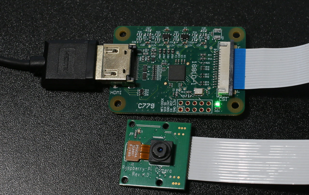
I recently setup the Simcom 7600 on a Jetson Nano. When I spoke of it I had mentioned that there is also a version of the cellular model that is specifically made for the Raspberry Pi. After a few delivery delays I have one in my hands and am looking at it now. Since both the Pi and the Jetson are Linux based ARM devices and the models are both using the same chipset my expectation is for the setup to be similar. There are two primary versions of the device. The version that I am using was released in 2020 December. There are some slight differences in the labels on the headers between these models. The version that I use is also without an SD card slot. Some of the older versions have these.

When you purchase a Simcom 7600, there is usually a letter following that number. The letter lets you know which variant that you have. Different variants are best supported by mobile networks in different regions. E-H work best in Southeast and West Asia, Europe, and Africa. A-H are primarily for North America, Australia, New Zealand, Taiwan, and Latin America.

The Simcom 7600 connects to a Pi the same way you would connect any other hat. Well, mostly. There are some options in how it is connected. The most obvious way is to connect the 4G hat to the 40-pin connector. I used this method. To do so, I had to remove the cooling fan that I had on my Pi. Included in the box are a couple of standoffs and screws for securing the 7600 to the board. Personally, I feel that a Pi that is using a mobile connection should also have its own battery. To secure the board and my batter I had to use a different set of standoffs. But I’ve got everything working (minus the cooling fan).

The Simcom 7600 for the Pi has a couple of USB ports and jumpers on it. Before powering it on, I went to the documentation to see what these were all for. Starting with the yellow header, there is a jumper already bridging PWR and 3V3. This is to set a power-on option. In this default state, the SIMCOM 7600 will turn on any time that it receives power. If the jumper is moved to bridge PWR and D6, then the SIMCOM 7600 will be off by default, but the Pi can control the power state itself. A user can also control the state through the power button on the side of the device. A third option is to remove the jumper entirely. If the jumper is removed then the only way to control the devices power state is manually using the power button.

In addition to controlling power, you now also have the option to place the device in flight mode. The control flight-mode with the pi, bridge pins D4 and Flight with a jumper. If the jumper is present then then flight mode is controllable through software.

Just behind the headphone jack are another set of jumpers. The purpose of these headers was not immediately obvious to me at first. They are not mentioned in the manual. But they show up on the schematic for the SIMCOM 7600. This header is for deciding how communication with the SIMCOM 7600 will occur.

SIMCOM 7600 Communication Jumpers

The pins that lead to the SIMCOM chip itself are the TXD 3.3V and RXD 3.3V. These lines pass through a line converter to raise the signals to the voltage level that the SIMCOM uses. If the jumpers are in their top position (connecting U_RX to TXD 3.3V and U_TX to RXD 3.3V) then communication with the SIMCOM will occur over USB (specifically USBJ1). In the middle position, communication with the SIMCOM occurs over the Raspberry PI 40 pin header on pins 8 and 10 (P_TX and P_RX). In the lowest position, the USB port connects to the Pi with there being no connection made to the SIMCOM chip.

There is a second USB port on the board. What is that for? The second USB port connects directly to the SIMCOM itself. It has USB interface pins on the chip itself. That means that there are two ways to communicate with the SIMCOM 7600 chip.

There are only a few lines on the 40-pin header that interact with the SIMCOM 7600. I could restore the heatsink and fan to my SIMCOM 7600 and still allow the Pi to communicate over USB along with a few other lines. But I prefer to have the board secured to the Pi.

Leaving the settings in their default state, I’ll be communicating with the SIMCOM 7600 over both USB and using the 40-pin header. To minimize the number of things that I could forget to do that would result in the board being non-responsive, I’m going to leave it bolted to the board though to keep it more secure.

Before setup, ensure that you’ve updated the packages on your Raspberry Pi

sudo apt-get update
sudo apt-get upgrade

Ensure that the serial port on the pi is enabled. From the Pi desktop upen the Pi menu, select “Preferences.” Then select “Raspberry Pi Configuration.” In the Interfaces tab select “Enable” next to the “Serial Port” item. If it were not enabled before, you will need to reboot after you enable it.

Shutdown your Pi and remove power from it. Attach the 4G hat to the Pi and power it back up. You should see the Power light on the Pi illuminated solid red. If the Pi detects a cellular signal, the Net light will blink. If it is solid, ensure that you have securely attached the antenna and have the SIM card in place.

Open a command terminal and type

sudo lsusb

You will see some serial devices listed. Connect the Pi and the cellular modem using the USB port that is next to the cellular antenna. Then, from the command terminal, run the lsusb command again. You should see an additional item of hardware. If you do, then the Pi has detected the modem.

Let’s get the software installed. The drivers for the modem are in a *.7z file. You will need to install a tool for unarchiving the file. You also need to have a tool for interacting with the serial port.

sudo apt-get install minicom p7zip-full

Download and unpackage the example code for the SIMCOM 7600. Along side this sample code is the driver that is needed for the Raspberry Pi.

wget https://www.waveshare.com/w/upload/2/29/SIM7600X-4G-HAT-Demo.7z
7z x SIM7600X-4G-HAT-Demo.7z -r -o/home/pi
sudo chmod 777 -R /home/pi/SIM7600X-4G-HAT-Demo

When the Pi boots up, we want it to initialize the SIMCOM board. To ensure this happens, open /etc/rc.local and add the following line.

sh /home/pi/SIM7600X-4G-HAT-Demo/Raspberry/c/sim7600_4G_hat_init

After initialization, you can start interacting with the Pi hat. As a test that it is responding, you can connect to it using the minicom utility and send some AT commands and see that is responds. You can connect to it using either port /dev/ttyUSB2 or /dev/ttyUSB3.

minicom -D /dev/ttyUSB2 -b 115200

Testing a Faraday Bag with AirTags

Among my many gadgets I have a Faraday Bag. Faraday bags are essentially a flexible version of a faraday cage. Such devices contain metalic content and prevent the passage of radio signals. You have probably seen various applications of this, such as wallets or envelops designed to prevent an NFC credit card from being read, or the metalic grid in the door of a Microwave oven that prevents the microwave radiation from getting out.

I won’t get into the physics of how these work. But it is worth noting that a Faraday cage may only work for a range frequencies. A cage that prevents one device from getting a signal might not have the same effect on another that uses a different frequency. While I’ve seen that my Faraday Bag has successfully blocked WiFi and cellular signals from reaching my phone and tablet, I wanted to see if it would work with an AirTag. For those unfamiliar, the AirTag is Apple’s implementation of a Bluetooth tracking device. Another well known Bluetooth tracker is from Tile. The fundamentals of how these devices work is essentially the same.

AirTags on top of Faraday Bag

The trackers are low-energy Bluetooth devices. If the tracker is near your phone, the phone detects the signal and the ID unique to the tracker. The phone takes notice where it was located when it looses signal to the tracker and generally assumes that the tracker is in the last place that it was when it received a signal. That isn’t always the case. The tracker my have been moved after the phone lost the signal (think of a device left in a taxi). The next method of locating that these devices use is that other people’s phones may see the tracker and relay the position. For the Tile devices anyone else that has the Tile app on their phone effectively participates in relaying the position of tiles that they encounter. For the AirTag anyone with a fairly recent iPhone and Firmware participates. My expectation is that that the ubiquity of the iPhone will make it the location network with more coverage. As a test, I gave an AirTag to a wiling participant and asked that they keep the device for a day. When I checked in on the location of the Device using the “Find My” app on the iPhone, I could see the person’s movements. On a commute to work, other iPhones that the person drove by on the Interstate reported the position. I could see the person’s location within a few minutes of them arriving at work.

There are some obvious privacy concerns with these devices. Primarily from an unwilling party having an AirTag put in their belongings. Apple is working on some solutions for some of the security concerns, though others remain. I thought about someone transporting a device with an AirTag that may not want their location located. One way to do this is to remove the battery. Another is to block the signal. Since I already have a Faraday Bag I decided to test out this second method.

I found that my Faraday Bag successfully blocks the AirTag from being detected or from receiving a signal. You can see the test in the above video. This addresses one of the concern for such trackers, though not all of them. This is great for an AirTag that one is knowingly transporting. For one that a person doesn’t realize is in their belongings, a method of detection is needed. For iPhone users, the iPhone is reported to alert a user if there is an AirTag that stays within their proximity that is not their own. Results from others testing this have been a bit mixed. The AirTags are also reportedly going to play an alert sound if they arenot within range of their owner for some random interval between 8 and 24 hours.

Presently, Android users would not get a warning. Though Apple is said to be working on an application for Android for detecting lingering AirTags. In the absence of such an application, I’ve tried using Bluetooth scanners on Android. The Airtag is successfully detected. The vendor (Apple) can be retrieved from the AirTag, but no other information is retrievable. I’ve got some ideas on how to specifically identify an AirTag within code for Android, but need to do more testing to validate this. This is something that I plan to return to later on.

I purchased this Faraday Bag some time ago. The specific bag that I have is, from what I have found, no longer available. But other comparable bags are available on Amazon.

Posts may contain products with affiliate links. When you make purchases using these links, we receive a small commission at no extra cost to you. Thank you for your support.


Faraday Bag for Phones

Faraday Bag for Tablets and Phones.

Silicon AirTag Case

Silicon AirTag Case

Twitter: @j2inet
Instagram: @j2inet
Facebook: j2inet
YouTube: j2inet

HDMI Capture on the Raspberry Pi

Back in January I tweeted about an HDMI capture device that for the Raspberry Pi. I’ve only recently have gotten a chance to use it. The device, known as the “HDMI to CSI-2 module”, works with the Raspberry Pi. Overall my experience was positive, though I found that this device has limitations that, if not previously known, can result in some frustration. The device connects to the CSI-2 camera interface and presents itself as a camera. The utilities and scripts that you may have used with the Raspberry Pi also work with this device without modifications. Along with the HDMI capture module the package contains the cable needed for connecting it to the full size Raspberry Pi and a second cable for use with a Raspberry Pi Zero.

One of the first uses that came to mind with this device is that I could use camera options beyond the official Pi cameras. The camera that I have about the house produce clean HDMI signals. They already have a range of lenses, ranging from some macro lenses for pictures of small items close-up and a 2132 millimeter Schmidt–Cassegrain for astrophotography.

My smallest lens next to my largest lens. Both of which are not available for use on the Pi through my digital camera.

The first time I tried to use the capture device with one of my cameras, it didn’t work. I received a non-descriptive error that is primarily associated with non-working or improperly installed cameras.

mmal: mmal_vc_component_enabled: failed to enable component: ENOSPC
mmal: camera component couldn't be enabled
mmal: main: Failed to create camera component
mmal: Failed to run camera app. Please check for firmware updates

Thankfully, this isn’t indicative of an actual hardware failure. The capture device works with a limited set of resolutions and refresh rates. For 1080p video signals, the maximum refresh rate is 25 fps.

ResolutionRefresh Rate (fps)
720p50
72060
1080i50
1080p24
1080p25
Supported Resolutions

After making adjustments to the output settings of my camera, I was successful in using it with the HDMI capture.

The camera was the first device that came to mind, but it could work with non-camera HDMI sources too. I connected a Nintendo Switch to the device and it captured from the switch just fine. Provided that the signal is within the resolution and FPS range and is not an encrypted (HDCP) signal, it works.

Comparing the HDMI capture device to the Raspberry Pi cameras, there were a few differences to note. While it may be easy to assume that the digital photo camera paired with this device is better than the Raspberry Pi cameras, that isn’t necessarily the case. “Better” is a matter of what satisfies the requirements for a solution. If that solution requires high physical portability, the photo camera’s size could be a disadvantage. Using an external camera also ads to external power needs; the external camera will need to have it’s own battery or power supply. The official Raspberry Pi cameras run off of the Raspberry Pi’s power.

HDMI to CSI-2 Module next to Raspberry Pi Camera

The Pi cameras offer some higher resolutions than one can capture with the HDMI capture device. Resolution is an attribute of quality, but not the only metric for quality. I hesitate to label the higher resolution as higher quality because there are cases where a lower resolution camera may be rated better on other quality metrics, such as clarity or dynamic range, or may have attributes that make it a better fit for a specific application, such as a different shutter angle.

The Raspberry Pi HQ camera (recognizable from it’s C-mount for attaching a lens) can capture still photographs of up to 4056×3040 pixels. The Raspberry Pi Camera v2 captures stills at up to 3280×2464 pixels. For video, all of the cameras have the same resolution. Keep in mind though at these higher resolutions since the device is receiving stills and not video frame the rate of capture will be much lower.

ResolutionFrame Rate (fps)
1080p30
720p60
480960/90
Raspberry Pi Camera Framerates

How did it work? After trying it on a Raspberry Pi with a Nintendo Switch I would rate the capture device as being okay. It isn’t stellar, but it isn’t bad either. It provides a way to interface with HDMI sources. During the process of recording, it appeared there were frames that were dropped. The playback confirmed this. I was wondering if the dropped frames were due to the speed of the memory card in the Pi or from some computational limits on its ability to encode the video to .H264. The next thought that came to mind was to try it with the Jetson Nano. Sadly, while the Jetson Nano uses the CSI-2 interface, at the time of this writing it is not compatible with the Jetson Nano.