While I enjoy being productive on my pi over SSH, there are times when I need to access the desktop environment. Rather then be bound to the display on which the Pi is connected (if it is connected to one, some of my Pis have no display) I decided to setup Remote Desktop on the Pi. Most of the computers that I use are Windows machines and already have a remote desktop client. (Note: another option is VNC). I did this for my Jetsons as well. While the same instructions often work on both the Jetson and the Pi, this is not one of the situations where that was the case. I have another entry coming on how to perform the necessary steps on the Jetson.
On the Pi, there are only a few steps needed. Like many installations, start with updating your packages. Open a terminal and enter the following commands.
sudo apt-get update
sudo apt-get upgrade
This could take a while to run depending on how long it has been since you last ran it and how many packages that there are to install. After it completes, use the following commands to install a remote desktop server to your Pi.
sudo apt-get install xrdp -y
sudo service xrdp restart
Once the installation is done, you need to get your Pi’s IP address.
ifconfig
You should see the addresses for your Pi’s network adapters listed. There will be several. My Pi is connected via ethernet. I need the address from the adapter eth0.
Response from ifconfig.
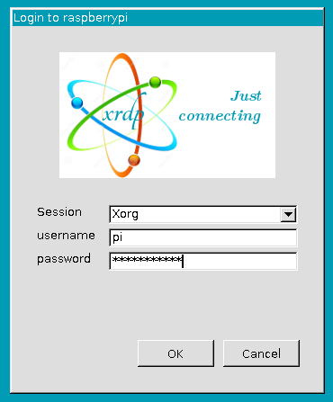
Once you have that information, you are ready co connect. Open the Remote desktop client in your computer and enter your Pi’s IP address as the identifier for the target machine. Once you enter it, you will be greeted with a second login screen that ask you information for the session your wish to start.
PI RDP Login
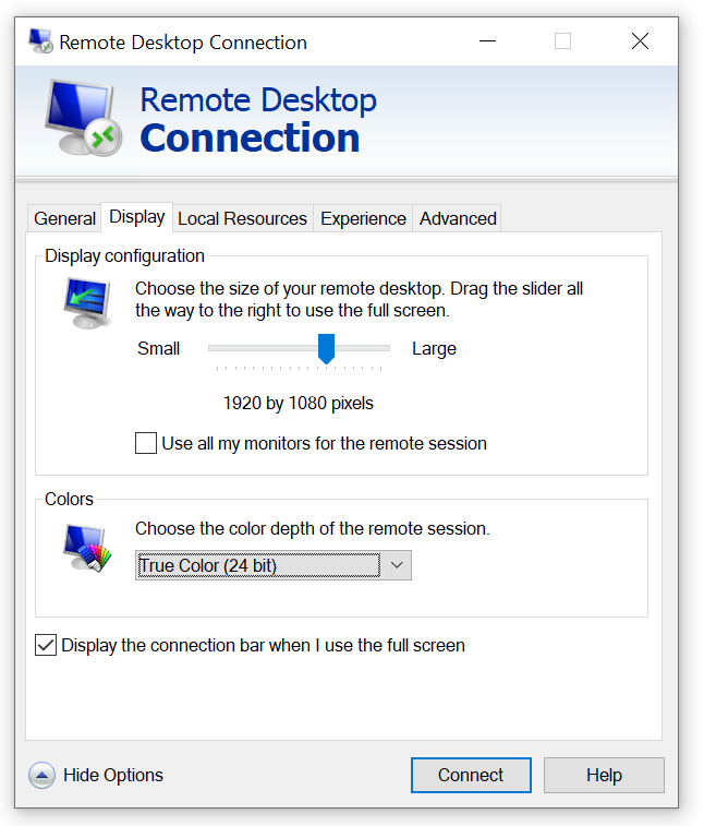
Leave the default setting of the Session as Xorg. Enter the user ID and password for your Pi. A few moments later you will see the Pis desktop. Note that while many remote desktop clients will default to using the resolution of your local computer’s display, you also have the option of setting a resolution manually. You may want to do this if you are on a slower network connection, or even if you just do not want your remote session to cover all of your local desktop.
Remote Desktop Client Resolution Settings
Posts may contain products with affiliate links. When you make purchases using these links, we receive a small commission at no extra cost to you. Thank you for your support.
I go through a lot more SD cards than a typical person. I’m usually putting these cards in single board computers like the Jetson Nano or the Raspberry Pi and am using them there. I have a lot of these devices. These cards only occasionally fail. But with a lot of devices “occasional” is frequent enough for my rate of card consumption to be higher than that of a typical consumer. The easy solution to this is to just not use SD cards. At this point, the Pi can boot of USB drives. I’ve generally resisted this for reasons of æsthetics. I just don’t like the U-shapped USB connector (feel free to tell me how silly that is in the comments section).
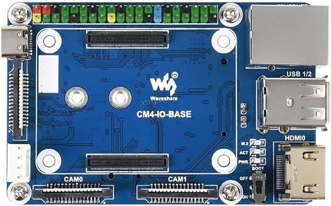
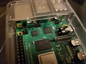
Enter the Raspberry Pi CM4. These modules have a PCIe interface, and you can select the board that has the hardware that you need. One of those boards is the WaveShare CM4-IO-Base. Among other hardware, this board has a PCIe M.2 keyed slot. There are two versions of this board, version A and version B. The main difference between these is the model B has a real time clock while the model A does not. Otherwise, these boards can be treated as identical
The CM4 IO-BASE-B that I am using sandwiched between acrylic cutouts.
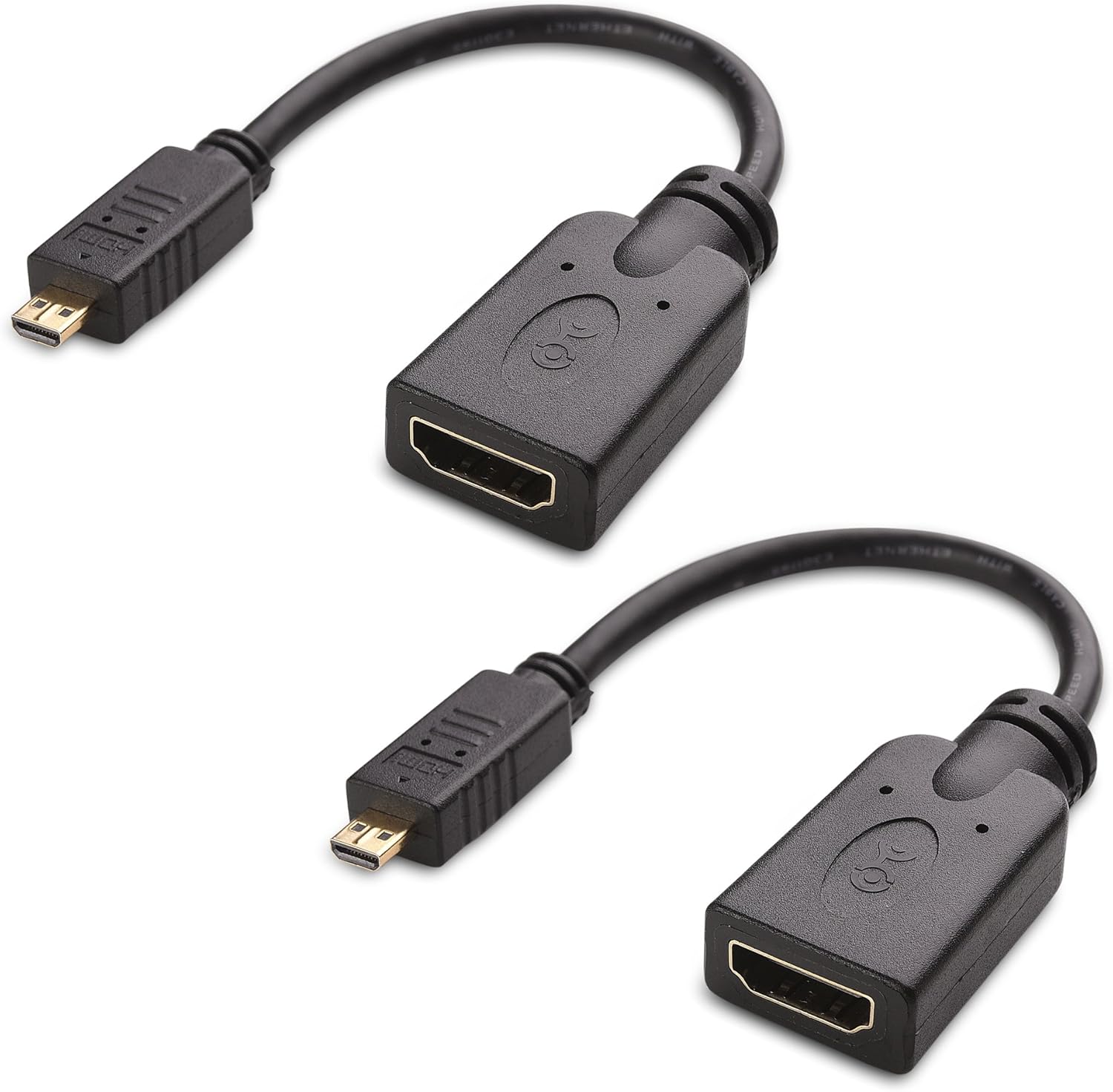
The CM4-IO-BASE has screw holes in positions that are identical to what one would expect for a Raspberry Pi 4B. This makes it compatible with a number of bases on which you might want to attach the board. It does differ from the Pi 4B in that it uses a full-sized HDMI port placed where two of the USB ports are on the Pi 4B. At first glance, it appears to give you less USB and HDMI options than the Pi 4B. But two USB connections and an HDMI connection is available from the underside of the board. You would need to purchase the HDMI+USB Adapter to use those or interface to them directly.
The top of the board has two connectors for cameras, and a connector for an external display. The feature of interest to me was the M.2 PCIe interface on the underside of the board. I decided on a M.2 2242 drive with 256 Gigs of capacity. I’ve seen drives of this size up to 2-terabytes in size (for significantly more).
Getting the Pi to bootup from the NVME isn’t hard. The Compute Module that I have has eMMC memory; that’s basically like having an SD card that you can’t remove. Getting the Pi to boot from the NVME drive involves writing the Pi OS to the MVNE drive and changing the boot order on the Pi. For changing the boot order on the Pi I needed another Linux device. I used another Raspberry Pi.
Writing the image to the NVME drive works in the same way that you would write the image to any other SD card. I happen to have some external NVME drive enclosures removed the drive from one of them and placed my Pi’s NCME drive in it. The Raspberry Pi Imager accepted the drive as a target and wrote the OS to it. The tricky part was modifying the boot order on the CM4.
NVME Drive Enclosure
The default boot order on the CM4 is 0xF461. This is something that didn’t make sense to me the first time that I saw it. The boot order is a numeric value that is best expressed as a hex number. Each digit within that number specifies a boot device. The Pi will start with the boot device that is specified in the lowest hex digit and try it first, and then go to the next hex digit.
For the boot order 0xF461 the Pi will try to boot to devices in the following order.
0x1 – Boot from the SD Card/eMMC
0x6 – Boot from the NVME drive
0x4 – Boot from a USB mass storage device
0xF – Reboot the pi and try again.
If you have a CM4 with no memory, this means that all you need to do to ensure that the right boot order is followed is to ensure that you don’t have an SD card connected to the board. You are ready to boot from the NVME drive. That’s not my scenario, I had more work to do. I updated the boot order alongside the Pi’s firmware. The CM4 is usually in one of two modes. It is either running normally, in which case the boot loader is locked, or it is in RPI Boot mode, in which case the bootloader can be written to, but the OS isn’t running. The CM4 cannot update its own bootloader. To update the bootloader, another computer is needed. I think that the best option for updating the boot loader is another Linux machine. In my case, I chose another Raspberry Pi.
The Raspberry Pi can already b picky about the power supplies that it works with. I used a USB-C power supply from a Raspberry Pi 400 (the unit built into the keyboard) for the following steps. The usual power supply that I used with my Pi wasn’t sufficient for powering 2 Pis. You’ll find out why it needed to work for 2 Pis in a moment. I used a Raspberry Pi 4B for writting the firmware to the CM4. To avoid confusion, I’m going to refer to these two devices as Programmer Device and the CM4.
On the CM4-IO-BASE board there is a switch or a jumper (depending on hardware revision) for switching the Pi to RPI Boot Mode. Set a jumper on this pin or turn the switch to “ON”. Connect the CM4 to the Programmer Device with a USB-A to USB-C cable. From the programmer device, you will need to replicate a GitHub repository that has all of the code that you need. Open a terminal on the Programmer Device, navigate to a folder in which you want to replicate the code, and use the following commands to clone and build the code.
git clone https://github.com/raspberrypi/usbboot --depth=1
cd usbboot
make
The code is now downloaded or built. Enter the recovery folder and edit the file named boot.conf to change the boot order.
cd recovery
nano boot.conf
At the time of this writing, that file looks like the following.
[all]
BOOT_UART=0
WAKE_ON_GPIO=1
POWER_OFF_ON_HALT=0

# Try SD first (1), followed by, USB PCIe, NVMe PCIe, USB SoC XHCI then network
BOOT_ORDER=0xf25641

# Set to 0 to prevent bootloader updates from USB/Network boot
# For remote units EEPROM hardware write protection should be used.
ENABLE_SELF_UPDATE=1
The line of interest is BOOT_ORDER=0xf25641. The comment in this file already lets you know how to interpret this line. You want the NVME drive (0x6) to be the first drive. To make that happen, the digit 6 needs to be the last digit. Change it to 0xf25416. With this change, the CM4 will try to boot from the NVME first and the eMMC second. IF you ever want to switch back to using the eMMC you only need to remove the NVME drive. There is a file named pieeprom.original.bin. This is going to be written to the CM4. To ensure that the CM4 has the latest [stable] firmware, downloaded the latest version from https://github.com/raspberrypi/rpi-eeprom/tree/master/firmware/stable and overwrite this file. Looking in that folder right now, I see the most recent file is only 15 hours old and named pieeprom-2022-02-10.bin. To download this from the terminal, use the following command.
After the file is downloaded, run the update script to assemble the new firmware image.
./update-pieeprom.sh
Navigate to the parent folder. Run the rpiboot utility with the recovery option to write the firmware to the device.
sudo ./rpiboot -d recovery
This command should only take a few seconds to run. When it is done you should see a green light blinking on the Pi signaling that it has updated its EEPROM. Disconnect the CM4 from the Programmer Device. Remove the jumper or set the RPI Boot switch to off. Connect the Pi to a display and power supply. You should for a brief moment see a message that the Pi is expanding the drive partition. After the device reboots it will be running from the NVME.
At this point my primary motivation for using the CM4-IO-BASE-B board has been achieved. But there is some additional hardware to consider. If you have the CM4-IO-BASE model B then there is a real time clock to setup. For both models, there is fan control available for setup.
Real Time Clock Setup
The real time clock interfaces with the Pi via I2C. Ensure that I2C is enabled on your Pi by altering the file boot/config.txt.
sudo nano /boot/config.txt
Find the line of the file that contains dtparam=audio=on and comment it out by placing a # at the beginning of the line. Add the following line to config.txt to ensure I2C is enabled.
dtparam=i2c_vc=on
Reboot the device. With I2C enabled you can now interact with the RTC through code. Waveshare provides sample code for reading and writing from the clock. The code in its default state is a good starting point, but not itself adequate for setting the clock. The code is provided for both the C language and Python. I’ll bu using the C-language version of the code. To download the code, use the following commands.
sudo apt-get install p7zip-full
sudo wget https://www.waveshare.com/w/upload/4/42/PCF85063_code.7z
7z x PCF85063_code.7z -O./
cd PCF85063_code
After downloading the code, enter the directory for the c-language project and build and run it using the following commands.
cd c
sudo make clean
sudo make -j 8
sudo ./main
You’ll see the output from the clock. Note that the clock starts from just before midnight of February 28, 2021 and progresses into March 1. The code has the starting date hard coded. Let’s look at the code in main.c to see what it is doing.
You can see where the time is set with the functions PCF85063_SetTime_YMD and PCF85063_SetTime_HMS. Let’s update this to use the date/time that the system is using. Place the following two lines above those two functions. This will only grab the system time and print it.
    time_t T = time(NULL);
    struct tm tm = *localtime(&T);

    printf("***System Date is: %02d/%02d/%04d***\n", tm.tm_mday, tm.tm_mon + 1, tm.tm_year + 1900);
    printf("***System Time is: %02d:%02d:%02d***\n", tm.tm_hour, tm.tm_min, tm.tm_sec);
Build and run the program again by typing the following two lines from the terminal.
sudo make -j 8
sudo ./main
This time the program will print the actual current date and time.
USE_DEV_LIB
Current environment: Debian
DEV I2C Device
DEV I2C Device
***System Date is: 20/03/2022***
***System Time is: 19:19:06***
21-2-28 23:59:58
21-2-28 23:59:59
21-3-1 0:0:0
21-3-1 0:0:1
21-3-1 0:0:2
21-3-1 0:0:3
21-3-1 0:0:4
Let’s pass in this information to the calls that set the date and set the time. The information that we need is in the tm structure. Note that in this structure the first month of the year is associated with the value 0. Also note that the tm structure stores the year as the number of years since 1900, while the RTC stores the year as the number of years since 2000. We need to shift the value by 100 to account for this difference. The updated lines of code look like the following.
    printf("***System Date is: %02d/%02d/%04d***\n", tm.tm_mday, tm.tm_mon + 1, tm.tm_year + 1900);
    printf("***System Time is: %02d:%02d:%02d***\n", tm.tm_hour, tm.tm_min, tm.tm_sec);
	PCF85063_SetTime_YMD(tm.tm_year - 100,tm.tm_mon + 1,tm.tm_mday);
	PCF85063_SetTime_HMS(tm.tm_hour,tm.tm_min,tm.tm_sec);
When you run the program again, you’ll see the current time. But how do we know the RTC is really retaining the time? One way is to run the program again with the calls that set the time commented out. One would expect the RTC to continue to show the real time based on the previous call. I tried this, and the RTC was printing out times from 01-01-01. Why did this happen?
I’ve not completely dissected the code, but I did fine that a call to PCF85063_init() at the beginning of main resets the clock. I just commented this out. With that call not being made, the time is retained. I use this call when setting the clock though. I’ve altered the program to accept a command line parameter. If setrtc is passed to the program as a command line argument it will set the time on the RTC. If setsystem is passed as the parameter then the program will attempt to set the system time. Setting the system time requires root privileges. If you try to set the time with this program without running as root then the attempt will fail.
The final version of this code is available in my GitHub account. You can find it here.
Fan Control
There’s a difference in the version A and version B for the fan control. On version A the fan is connected to port 18. It can be turned on and off by changing the state of this pin. For version B the fan is controlled through the I2C bus. Example code is also provided for fan control on version B. To download the fan code for version-B use the following commands from the terminal.
sudo apt-get install p7zip-full
sudo wget https://www.waveshare.com/w/upload/5/56/EMC2301_code.7z
7z x EMC2301_code.7z -O./
cd EMC2301_code
To build the code, use the following commands.
cd c
sudo make clean
sudo make -j 8
sudo ./main
Let’s look at a highly abridged version of the code.
Fan control is straight forward. After some setup calls, the fan speed can be set by writing to EMC2301_writeTachoTarget(). The call to EMC2301_fetchFanSpeed() will read the current fan speed. Through repeated calls to this function you can see the acceleration of the fan when the speed is changed.
Other Hardware
Take note that a number of interfaces are disabled by default on the CM4. This includes the USB-C, the two DSI camera ports, and the display connector. If you need to use any of these, the resources page for this board has the information that needs to be added to the
Conclusion
Pi setup for this board was pretty easy. I’d definitely consider getting another one. If I had to do things all over again though I would double-check my cables. There was a moment when I thought things were not working because I wasn’t getting a video signal. It turns out that I had two HDMI cables close to each other that I thought was a single cable. I didn’t get a video signal because I had connected to a cable that was not terminating at my display (time to consider cable organization). This is a great board if you need a Pi that is close to the usual form factor but with more memory. I might consider another if I can acquire another CM4 (which is difficult in this chip shortage).
Posts may contain products with affiliate links. When you make purchases using these links, we receive a small commission at no extra cost to you. Thank you for your support.
As part of an exploration on hosting sites and services with a minimal hardware setup, I wanted to install WordPress on a Raspberry Pi. WordPress is an open-source software system for hosting sites and blogs. I’m trying it out because I thought it would be easy to install and setup and allow someone to manage posts without demanding they be familiar with HTML and other web technologies (though knowing them certainly helps). With the Raspberry Pi being an ARM based Linux computer, I also thought that these instructions might work on a NVIDIA Jetson with little alteration. When I tried it out, I found that these instructions work on the Jetson with no alteration needed at all. In this post I only show how to install WordPress and its dependencies. I’ll cover making the device visible to the Internet in a different post.
To get started, make sure that your Jetson or Raspberry Pi is up to date. Run the following two commands.
sudo apt-get update
sudo apt-get upgrade
These commands could take a while to run. Once they have finished, reboot your device.
Not to install the software. I’m connected to my device over SSH. You can run these commands directly through a terminal on the devicealso. But everything that I write is from the perspective of having access only to the terminal. We are going to install the Apache web server, a MySQL database, and a PHP interpreter.
Apache Web Server
To install the Apache Web Server, type the following command.
sudo apt-get install apache2
After running for a while, Apache should successfully install. You can verify that it is installed by opening a browser to your device’s IP address. From the terminal, you can do this with the following command.
lynx http://localhost
You should see the default Apache page display. To exit this browser press the ‘Q’ key on your keyboard and answer ‘y’ to the prompt.
Installing PHP
To install PHP on your device, use the following command.
sudo apt-get install php
With the PHP interpreter in place, we can add a page with some PHP code to see it processed.
Navigate to the folder that contains the Apache HTML content and add a new page named test-page.php
cd /var/www/html
sudo nano test-page.php
The file will have a single line as its content. Type the following.
<?php echo "Hey!"; ?>
You can now navigate to the page in a browser.
lynx http://localhost/test-page.php
Installing the Database
Maria Database is a mySQL database. It will contain the content for our site. Install it with the following command.
sudo apt-get install mariadb-server
The database is installed, but it needs to be configured. To access it, we need to setup a user account and a password. Decide what your user ID and password will be now. Also choose a name for the database. You will need to substitute my instances of USER_PLACEHOLDER, PASSWORD_PLACEHOLDER, and DATABASE_PLACEHOLDER with the names and passwords that you have chosen.
sudo mysql -uroot
You will be presented with the MariaDB prompt. Type the following commands to create your user account, database, and to give permission to the database.
CREATE USER 'USER_PLACEHOLDER'@'localhost' IDENTIFIED BY 'PASSWORD_PLACEHOLDER';
CREATE DATABASE DATABASE_PLACEHOLDER;
GRANT ALL ON DATABASE_PLACEHOLDER.* to 'USER_PLACEHOLDER'@'localhost';
quit;
We need to make sure that account can access the database. Let’s connect to the database using the account that you just created.
mysql -u USER_PLACEHOLDER -p
You will be prompted to enter the password that you choose earlier. After you are logged in, type the following to list the databases.
SHOW DATABASES;
A list of the databases will show, which should include a predefined system database and the one you just created.
We also need to install a package so that PHP and MySQL can interact with each other.
sudo apt-get install php-mysql
Installing WordPress
The downloadable version of WordPress can be found at wordpress.org/download. To download it directly from the device to the web folder use the following command.
We are about to access our site. It can be accessed through the devices IP address at http://IP_ADDRESS_HERE/wordpress. As a personal preference, I would prefer for the site suffix to be something other than wordpress. I’m changing it to something more generic, “site”.
mv wordpress site
Now let’s restart Apache.
sudo service apache2 restart
From here on I am going to interact with the device from another computer with a desktop browser. I won’t need to do anything in the device terminal. Using a browser on another computer I navigate to my device’s IP address in the /site folder. The IP address of my device is 192.168.50.216. The complete URL that I use is http://192.168.50.216/site. When I navigate there, I get prompted to select a language.
Word Press Language Prompt
The next page lets you know the information that you will need to complete the setup. That information includes
The database name
The database user name
The database password
The database host
The Table name prefix
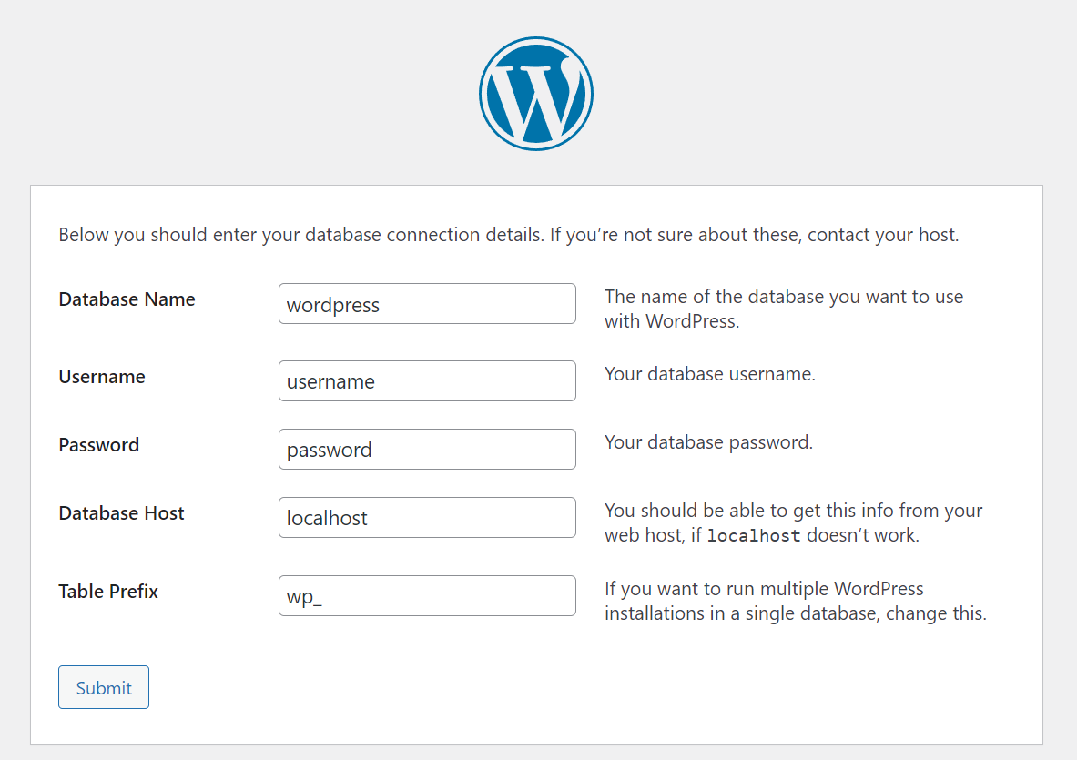
The first three items should be familiar. The fourth item, the database host, is the name of the machine that has the database. Since we are running the database and WordPress from the same device this entry will be “localhost”. If we were running more than one site from this device to keep the databases separate, the tables for each instance could have a common prefix. I’m going to use the prefix wp_ for all of the tables. All of this information will be saved to a file named wp-config.php. If you need to change anything later your settings can be modified from that file.
Default WordPress Settings
Enter your database name, user name, and password that you decided earlier. Leave the host name and the table prefix with their defaults and click on “submit.” If you entered everything correctly, on the next screen you will be prompted with a button to run the installation.
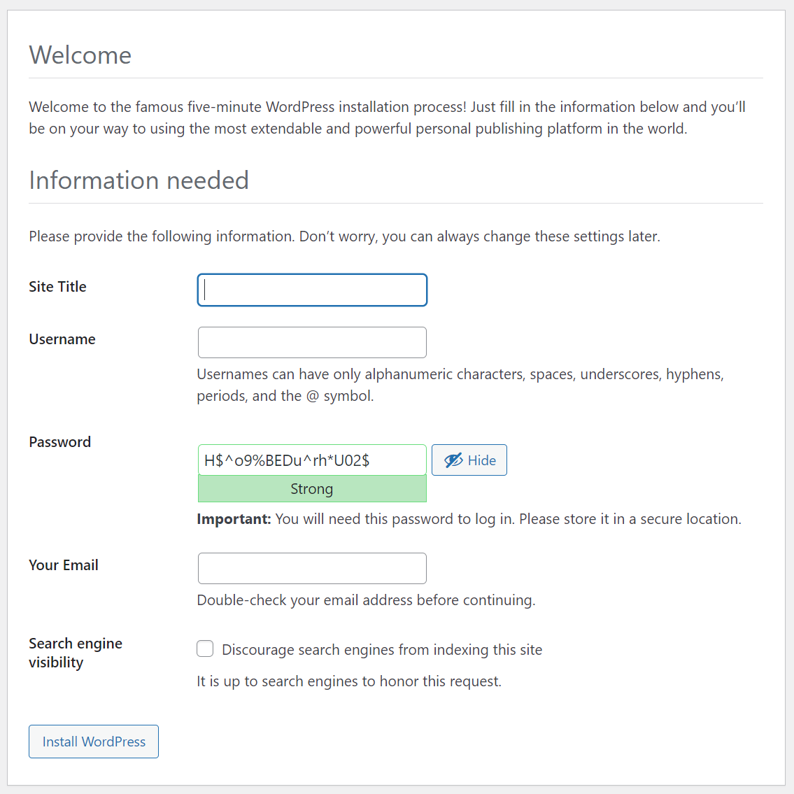
On the next page you must choose some final settings of your Word Press configuration.
Final Setup Screen
After clicking on “Install WordPress” on this screen, you’ve completed the setup. With the instructions as I’ve written them, the site will be in the path /wordpress. The administrative interface will be in the path /wordpress/wp-admin. WordPress is easy to use, but a complete explanation of how it works could be lengthy and won’t be covered here.
Creating a service on a Raspberry Pi or a Jetson is easier than I thought. At the same time, there is still a lot of information to sort through. I’m still exploring the various settings that can be applied to a service. But I wanted to share the information that I thought would be immediately useful. While I was motivated to explore this based on something I was doing on a Jetson Nano, the code and instructions work identically without any need for modification on a Raspberry Pi.
I have a Jetson Mate. The Jetson Mate is an accessory for the Jetson Nano or Jetson Xavier NX Modules. Up to 4 modules can be placed within the Jetson mate to form a cluster. Really the Jetson Mate is just a convenient way to power multiple Jetsons and connect them to a wired network. It contains a 5-port switch so that a single Network cable can be used to connect all of the modules. Despite the Jetsons being in the same box, they don’t have an immediate way to know about each other. Reading the documentation from Seeed Studio, they suggest logging into your router and finding the IP addresses there.
That approach is fine when I’m using the Jetsons from my house; I have complete access to the Network here. But that’s not always possible. On some other networks I may not have access to the router settings. I made a program that would let the Jetson’s announce their presence over UDP Multicast. This could be useful on my Pis also; I run many of them as headless units. I needed for this program to start automatically after the device was powered on and to keep running. How do I do that? By making it a service.
There are several ways that one could schedule a task to run on Linux. I’m using systemd. Systemd was designed to unify service configurations across Linux distributions. The information shown here has applicability well beyond the Pi and Jetson.
The details of how my discovery program works is a discussion for another day. Let’s focus on what is necessary for making a service. For a sample service, let’s make a program that does nothing more than increment a variable and output the new value of the variable. The code that I show here is available on GitHub ( https://github.com/j2inet/sample-service ). But it is small enough to place here also. This is the program.
#include <iostream>
#include <thread>

using namespace std;

int main(int argc, char** argv)
{
    int counter = 0;
    while(true)
    {
        cout << "This is cycle " << ++counter << endl;
        std::this_thread::sleep_for(std::chrono::seconds(10));
    }
}
This program counts, outputting a digit once ever ten seconds. To build the program, you will need to have cmake installed. To install it, use the following command at the terminal.
sudo apt-get install cmake -y
Once that is installed, from the project directory only a couple of commands are needed to compile the program.
cmake ./ make
The program is built, and a new executable named service-sample is now in the folder. If you run it, you will see the program counting. Press CTRL-C to terminate the program. Now we are going to make it into a service.
To make a service, you will need to copy the executable to a specific folder and also provide a file with the settings for the service. For the service settings, I’ve made a file named similarly to the executable. This isn’t a requirement. But it’s something that I’ve chosen to do for easier association. In a file named service-sample.service I’ve place the settings for the service. Many of these settings are technically optional; you only need to set many of them if your specific service is dependent on them. I’m showing more than is necessary for this service because I think some of these settings will be useful to you for other projects and wanted to provide an example.
Here are what some of those settings mean. Note that I also describe some other settings that are not used, but available for you to consider. You can also see documentation for this file in the man pages.
[Unit] section
Documentation viewable with the following command
man systemd.unit
Setting
Meaning
Description
A short text description of the service.
Documentation
URIs at which documentation for the service can be found
Requires
Other units that will be activated or deactivated in conjunction with this unit
Wants
Express weak dependencies. Will try to activate these dependencies first, but if those dependencies fail, this unit will be unaffected
Conflicts
This setting prevents this unit from running at the same time as a conflicting unit
After/Before
Used to express the order in which units are started.These settings contain a space delimited list of unit names.
[Install] Section
Documentation for the [Install] section is viewable at the following URL
Setting
Meaning
RequiredBy / WantedBy
Starts the current service if any of the listed services are started. WantedBy is a weaker dependency than RequiredBy.
Also
Specifies services that are to be started or disabled along with this service
[Service] Section
Documentation for the [Service] section is viewable from the following URL.
man systemd.service
Setting
Meaning
Type
* simple – (default) starts the service immediately * forking – the service is considered started once the process has forked and the parent has exited * oneshot – similar to simple. Assumes service does its job and exits. * notify – considers a service started when it sends a signal to systemd
ExecStart
Commands with arguments to execute to start the service. Note that when Type=oneshot that multiple commands can be listed and executed sequentially.
ExecStop
Commands to execute to stop the service
ExecReload
Commands to execute to trigger a configuration reload of the service
Restart
When this option is enabled, the service will be restarted when the service process exits or is killed
RemainAfterExit
When True, the service is considered active even after all of its processes have exited. Mostly used with Type=oneshot.
Deploying
Having the executable and this service file are not themselves enough. They must also be moved to an appropriate location and the service must be activated. I’ve placed the steps for doing this in a script. This script is intentionally a bit verbose to make it clear what the script is doing at any time. The first thing that this script does is terminate the service. While this might sound odd given that we haven’t installed the service yet, I do this to make the script rerunnable. If this is not the first time that the script has run, it is possible that the service process is running. To be safe, I terminate it.
Next, I copy files to their appropriate locations. For this simple service those files are one executable binary and the service settings. The executable is placed in /usr/local/bin. The service settings are copied to /etc/systemd/system/. On the service settings, the permissions on it are changed with chmod. This will ensure the owner has read/write permissions and the group has read permissions.
With the files for the service in place, we next ask systemd to reload the service definitions. I then probe the status for my service. While my service isn’t running, I should see it listed. I then enable the service (so that it will run on system startup) and then start the service (so that I don’t need to reboot to see it running now) and then probe the system status again.
echo "stopping service. Note that the service might not exists yet."
sudo systemctl stop service-sample

echo "--copying files to destination--"
sudo cp ./service-sample /usr/local/bin
sudo cp ./service-sample.service /etc/systemd/system/service-sample.service
echo "--setting permissiongs on file--"
sudo chmod 640 /etc/systemd/system/service-sample.service
echo "--reloading daemon and service definitions--"
sudo systemctl daemon-reload
echo "--probing service status--"
sudo systemctl status service-sample
echo "--enabling service--"
sudo systemctl enable service-sample
echo "--starting service service status--"
sudo systemctl start service-sample
echo "--probing service status--"
sudo systemctl status service-sample
After the service is installed and running, you can use the command for probing the status to see what it is up too. The last few lines that the service has outputted will display with the service information. Probe the service status at any time using this command.
sudo systemctl status service-sample
Sample output from the command follows.
pi@raspberrypi:~ $ sudo systemctl status service-sample
● service-sample.service - Counting service.
   Loaded: loaded (/etc/systemd/system/service-sample.service; enabled; vendor preset: enabled)
   Active: active (running) since Wed 2022-03-09 15:57:12 HST; 12min ago
 Main PID: 389 (service-sample)
    Tasks: 1 (limit: 4915)
   CGroup: /system.slice/service-sample.service
           └─389 /usr/local/bin/service-sample

Mar 09 16:09:29 raspberrypi service-sample[389]: This is cycle 361
Mar 09 16:09:31 raspberrypi service-sample[389]: This is cycle 362
Mar 09 16:09:33 raspberrypi service-sample[389]: This is cycle 363
Mar 09 16:09:35 raspberrypi service-sample[389]: This is cycle 364
Mar 09 16:09:37 raspberrypi service-sample[389]: This is cycle 365
Mar 09 16:09:39 raspberrypi service-sample[389]: This is cycle 366
Mar 09 16:09:41 raspberrypi service-sample[389]: This is cycle 367
Mar 09 16:09:43 raspberrypi service-sample[389]: This is cycle 368
Mar 09 16:09:45 raspberrypi service-sample[389]: This is cycle 369
Mar 09 16:09:47 raspberrypi service-sample[389]: This is cycle 370
pi@raspberrypi:~ $
Screenshot of service output. Note the green dot indicates the service is running.
The real test for the service comes after reboot. Once you have the service installed and running on your Jetson or your Pi, reboot it. After it boots up, probe the status again. If you see output, then congratulations, your service is running! Now that a service can be easily created and registered, I’m going to refine the code that I used for discovery of the Pis and Jetsons for another post.
Posts may contain products with affiliate links. When you make purchases using these links, we receive a small commission at no extra cost to you. Thank you for your support.
I’ve previously talked about video capture on the Raspberry Pi using an HDMI device that interfaced with the camera connector. Today I’m looking at using USB capture devices. USB capture devices often present as web cams. The usual software and techniques that you may use with a webcam should generally work here.
The two devices that I have are the Elgato CamLink 4K and the Atmos Connect. Despite the name, the CamLink 4K does not presently work in 4K mode for me on the Pi. (I’m not sure that the pi would be able to handle that even if it did). I am using a Raspberry Pi 4. I got better results with the Atmos Connect; it is able to send the Pi pre-compressed video so that the pi didn’t have to compress it.
Hardware setup is simple. I connected the USB capture device to the pi and connected an HDMI source to the capture device. If you want to be able to monitor the video while it is captured you will also need an HDMI splitter; the Pi does not show video while it is being captured. Most of what needs to be done will be in the Raspberry Pi terminal.
If you want to ensure that your capture device was detected you can use the lsusb command. This command lists all the hardware detected on the USB port. If you can’t recognize a device there, using it, disconnecting a device, using it again, and noting the difference will let you know identify a line in the output to an item of hardware. Trying first with the Elgato CamLink, my device was easily identified. There was an item labeled as Elgato Systems GmbH.
I’ve not been able to make the devices work with raspistill or raspivid, but it works with ffmpeg and video for linux (v4l-utils). To install Video 4 Linux, use the following command.
sudo apt install v4l-utils
Once Video 4 Linux is installed, you can list the devices that it detects and the device file names.
v4l2-ctl --list-devices
In addition to hardware encoders, I get the following in my output.
Cam Link 4K: Cam Link 4K (usb-0000:01:00.0-2):
          /dev/video0
          /dev/video1
The device name of interest is the first, /dev/video0. Using that file name, we can check what resolutions that it supports with ffmpeg.
$ ffmpeg -f v4l2 -list_formats all -i /dev/video0

[video4linux2,v4l2 @ 0xcca1c0] Raw     :    yuyv422:      YUYV 4:2:2 : 1920x1080
[video4linux2,v4l2 @ 0xcca1c0] Raw     :       nv12:      YUYV 4:2:2 : 1920x1080
[video4linux2,v4l2 @ 0xcca1c0] Raw     :   yuyv420p:      YUYV 4:2:0 : 1920x1080
For this device, the only resolution supported in 1920×1080. I have three options for my format, yuyv422m nv12, and yuyv420p. Before we start recording, let’s view the input. With the following command, we can have ffmpeg read from our video capture device and display the HDMI video stream on the screen.
In your case, the format (nv12), resolution, and hardware file name may need to be different. If all goes well after running that command, you will see the video stream. Let’s have the video dump to a file now.
This command will send the recorded data to an AVI file. AVI is one of the envelope formats in which audio, video, and other data can be packaged together. You will probably want to convert this to a more portable format. We can also use ffmpeg to convert the output file from AVI to MP4. I’m going to use H264 for video encoding and AAC for audio encoding.
You can find an audio entry on this blog post on Spotify!
Those of you that follow me on Instagram, you may have seen a picture of the equipment that I use to record the video walkthrough of how to do this. A list of those items used is below. Note that these are Amazon Affiliate links.
I recently setup the Simcom 7600 on a Jetson Nano. When I spoke of it I had mentioned that there is also a version of the cellular model that is specifically made for the Raspberry Pi. After a few delivery delays I have one in my hands and am looking at it now. Since both the Pi and the Jetson are Linux based ARM devices and the models are both using the same chipset my expectation is for the setup to be similar. There are two primary versions of the device. The version that I am using was released in 2020 December. There are some slight differences in the labels on the headers between these models. The version that I use is also without an SD card slot. Some of the older versions have these.
When you purchase a Simcom 7600, there is usually a letter following that number. The letter lets you know which variant that you have. Different variants are best supported by mobile networks in different regions. E-H work best in Southeast and West Asia, Europe, and Africa. A-H are primarily for North America, Australia, New Zealand, Taiwan, and Latin America.
The Simcom 7600 connects to a Pi the same way you would connect any other hat. Well, mostly. There are some options in how it is connected. The most obvious way is to connect the 4G hat to the 40-pin connector. I used this method. To do so, I had to remove the cooling fan that I had on my Pi. Included in the box are a couple of standoffs and screws for securing the 7600 to the board. Personally, I feel that a Pi that is using a mobile connection should also have its own battery. To secure the board and my batter I had to use a different set of standoffs. But I’ve got everything working (minus the cooling fan).
The Simcom 7600 for the Pi has a couple of USB ports and jumpers on it. Before powering it on, I went to the documentation to see what these were all for. Starting with the yellow header, there is a jumper already bridging PWR and 3V3. This is to set a power-on option. In this default state, the SIMCOM 7600 will turn on any time that it receives power. If the jumper is moved to bridge PWR and D6, then the SIMCOM 7600 will be off by default, but the Pi can control the power state itself. A user can also control the state through the power button on the side of the device. A third option is to remove the jumper entirely. If the jumper is removed then the only way to control the devices power state is manually using the power button.
In addition to controlling power, you now also have the option to place the device in flight mode. The control flight-mode with the pi, bridge pins D4 and Flight with a jumper. If the jumper is present then then flight mode is controllable through software.
Just behind the headphone jack are another set of jumpers. The purpose of these headers was not immediately obvious to me at first. They are not mentioned in the manual. But they show up on the schematic for the SIMCOM 7600. This header is for deciding how communication with the SIMCOM 7600 will occur.
The pins that lead to the SIMCOM chip itself are the TXD 3.3V and RXD 3.3V. These lines pass through a line converter to raise the signals to the voltage level that the SIMCOM uses. If the jumpers are in their top position (connecting U_RX to TXD 3.3V and U_TX to RXD 3.3V) then communication with the SIMCOM will occur over USB (specifically USBJ1). In the middle position, communication with the SIMCOM occurs over the Raspberry PI 40 pin header on pins 8 and 10 (P_TX and P_RX). In the lowest position, the USB port connects to the Pi with there being no connection made to the SIMCOM chip.
There is a second USB port on the board. What is that for? The second USB port connects directly to the SIMCOM itself. It has USB interface pins on the chip itself. That means that there are two ways to communicate with the SIMCOM 7600 chip.
There are only a few lines on the 40-pin header that interact with the SIMCOM 7600. I could restore the heatsink and fan to my SIMCOM 7600 and still allow the Pi to communicate over USB along with a few other lines. But I prefer to have the board secured to the Pi.
Leaving the settings in their default state, I’ll be communicating with the SIMCOM 7600 over both USB and using the 40-pin header. To minimize the number of things that I could forget to do that would result in the board being non-responsive, I’m going to leave it bolted to the board though to keep it more secure.
Before setup, ensure that you’ve updated the packages on your Raspberry Pi
sudo apt-get update
sudo apt-get upgrade
Ensure that the serial port on the pi is enabled. From the Pi desktop upen the Pi menu, select “Preferences.” Then select “Raspberry Pi Configuration.” In the Interfaces tab select “Enable” next to the “Serial Port” item. If it were not enabled before, you will need to reboot after you enable it.
Shutdown your Pi and remove power from it. Attach the 4G hat to the Pi and power it back up. You should see the Power light on the Pi illuminated solid red. If the Pi detects a cellular signal, the Net light will blink. If it is solid, ensure that you have securely attached the antenna and have the SIM card in place.
Open a command terminal and type
sudo lsusb
You will see some serial devices listed. Connect the Pi and the cellular modem using the USB port that is next to the cellular antenna. Then, from the command terminal, run the lsusb command again. You should see an additional item of hardware. If you do, then the Pi has detected the modem.
Let’s get the software installed. The drivers for the modem are in a *.7z file. You will need to install a tool for unarchiving the file. You also need to have a tool for interacting with the serial port.
sudo apt-get install minicom p7zip-full
Download and unpackage the example code for the SIMCOM 7600. Along side this sample code is the driver that is needed for the Raspberry Pi.
When the Pi boots up, we want it to initialize the SIMCOM board. To ensure this happens, open /etc/rc.local and add the following line.
sh /home/pi/SIM7600X-4G-HAT-Demo/Raspberry/c/sim7600_4G_hat_init
After initialization, you can start interacting with the Pi hat. As a test that it is responding, you can connect to it using the minicom utility and send some AT commands and see that is responds. You can connect to it using either port /dev/ttyUSB2 or /dev/ttyUSB3.
The Raspberry Pi has a few more power options than what one might gather from a quick glance. With the exception of the computer modules (which will get no further mention here) the Pis have a USB port for providing power. The Pi-4 has a USB-C port while the other units use micro-USB. In most cases having a 5-volt power supply with a the appropriate USB interface is sufficient. Using the USB interface, the Pi can be powered through a phone charger. This includes portable chargers, which might be used if the Pi needs to be placed where outlets are not available or if they must be movable. The USB port isn’t the only way to power the Pi though.
View this content in Video Form
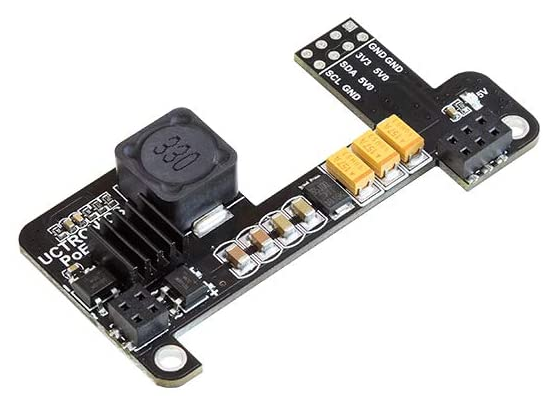
Another way of powering the Pi is through the 40-pin connector. There are pins labeled 5V and GND. these pins are often used as a voltage output. But these pins can also be used as a voltage input. Applying appropriate voltage to these pines will power the Pi on. In addition to applying 5-volts directly, there are also Pi-hats made for interfacing to these pins. On the Pi-4 and Pi-3, just behind the Ethernet connector, there are 4 pins. These pins connect to the unused connections in the Ethernet jack. With a Power over Ethernet (PoE) hat, voltage supplied over these pins can be passed through a voltage regulator and then fed into the Pi.
Pi PoE Pins
To use this there are a few conditions that must be met. If you are considering this this solution then you will undoubtedly be using the Pi with a wired network connection. You also need a means of injecting power into the network. Some routers have this functionality build in. For routers that do not, there are various forms of PoE power injectors. With this solution a headless Pi only needs one cable for providing a network connection and a the power. Such hats are available in a number of form-factors. My preference is towards the one of the minimalist PoE adapters.
If you have a Pi that doesn’t support PoE, you are not out of luck! You can still take advantage of it with adapters for extracting power from the extra lines and routing it to the USB input on your Pi.
Another way of powering a Pi is with batteries. While it is possible to take consumer batteries (AA or AAA batteries) and power a Pi with those, I would not suggest it. There are options available with higher capacities and other features that are worth considering. In looking at a battery solution not only might you want to consider the battery capacity, but the inclusion of a real time clock and the ability to query the power level of the batteries. The most basic solutions only provided power and a USB port for charging the battery.
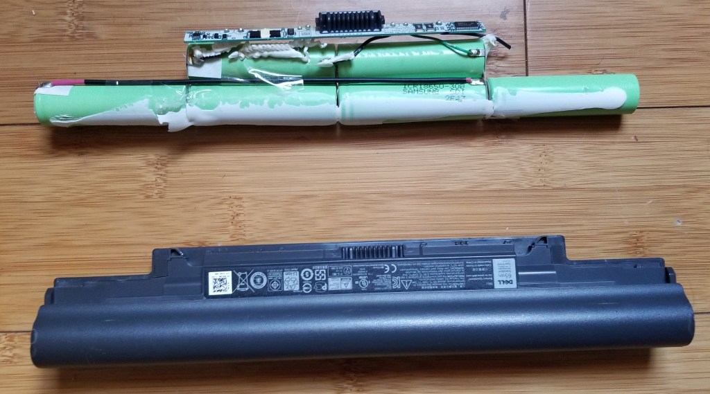
Many of the solutions use 18650 batteries. So named because they are 18mm in diameter and 65mm long. These cells look a lot like enlarged AA batteries. Even if you don’t recognize them, you’ve probably encountered these batteries before in laptop computers. Unlike the diminutive consumer batteries of similar shape, these cells rate at having a nominal voltage of 3.7 volts each. With two batteries together they are able to meet and exceed the 5-volt power requirement for the Pi. Power regulation circuits within the battery adapters ensure that the power delivered to the Pi doesn’t exceed 5-volts.
A laptop battery that has been opened up to show the 18650 batteries from the inside.
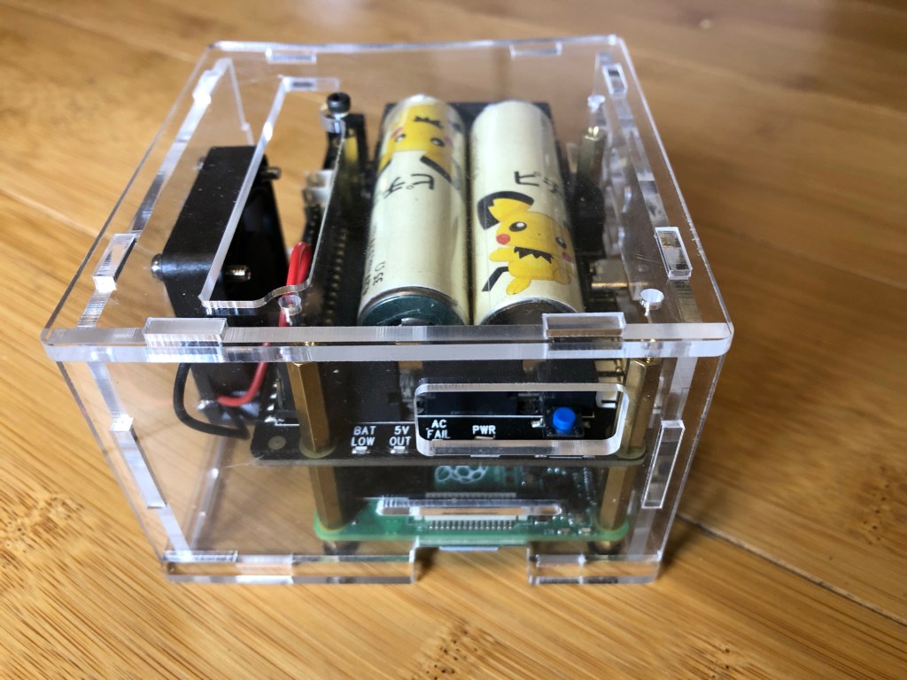
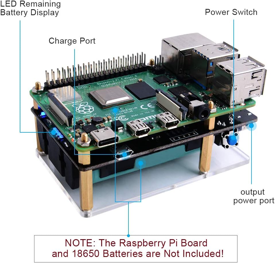
One of my favourite is the Geekworm X728. This unit contains a real-time clock and has scripts available for probing the state of the battery. The unit allows settings for having the pi automatically startup when power is applied and shutting down when when the battery level is low. For increasing the battery capacity, additional pairs of batteries can be added to the X728-A2 . The X728-A2 is made only for connecting to the X728 and add additional batteries. Though if you have the know-how, you can connect additional batteries in parallel to the ones in the X728. The board shows the power level through three LEDS on the side. There’s also a dedicated power-button on the board for powering up and shutting down.
X728 In an Acrylic Case
In close second is the PiJuice. Right now the PiJuice is a lot more expensive than the X728 at almost twice the price. But it has an additional feature; the PiJuice allows scripts to be scheduled to run under specific power or time conditions. While the battery included with the PiJuice has lower capacity than a pair of 18650 batteries, there are use cases under which it could have longer usage before requiring a charge. On the PiJuice the Pi can be put to sleep, consuming much less power, and then wake up to perform some work and go back to sleep.
The PiJuice mounted to the back of a Pi 3B
The last battery kit I want to mention is sold under various names. When I ordered one, it was branded under GeekPi. While that specific SKU is no longer available, the same unit is available branded from MakerHawk. It is often described as a UPS (Uninterruptible Power Supply). It is the least expensive of the battery kits, costing less than half the price of either of the other two. But it doesn’t have any way for the pi to detect the battery level or a way to have the Pi react to power events. It only provides power and nothing more. Like the X728, one could connect additional batteries in parallel to increase the available energy.
All of the battery solutions can also function as a UPS; if external power fails your Pi would be able to continue working. I’ve been able to keep the Pis running for hours at a time (days in the case of the Pi Juice on a wake/sleep schedule). I love the overall compactness of the the battery solutions made for the Pi. Some time in the future I plan to present one of the Pi based solutions that I made using the batteries.
Posts may contain products with affiliate links. When you make purchases using these links, we receive a small commission at no extra cost to you. Thank you for your support.
I stumbled upon a thread in the Raspberry Pi forums about enabling networking on the USB-C port on the Raspberry Pi 4. At first glance I thought this would be about networking with a USB-C to Ethernet dongle. It’s not. It is about configuring the Raspberry Pi to present as a network adapter when connected to another device with a USB-C cable. While this might sounds like a rather pedestrian capability at first it is something that has a lot of potential. I see using this when I want to do development on the Pi and I’m in an environment in which a network isn’t available (such as when I’m on a long plane trip) or when there’s a network but I just can’t connect the Pi to it (such as on a corporate network). Additionally since I expect my Android tablet to loose it’s ability to run Linux this provides a portable dev environment in which I can put the capabilities that I need.
The basic steps in what to do can be found on this thread posted by the user thagrol. The steps are simple. I am re-posting the steps here.
Open /boot/config.txt and add the line dtoverlay=dwc2
Open /boot/cmdline.txt and append the following modules-load=dwc2,g_ether
Reboot the Pi
After doing these steps when the Pi is connected to a computer the computer will see it as a networking device. If you list the network adapters on the Pi you will see a new network adapter with the name usb0.
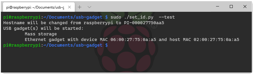
thagrol notes that the mac address generated for both sides of this virtual network adapter will be different every time that the service is started. This can cause issues when using DHCP. He provides a solution in the form of a script that will generate a set of MAC addresses based on a unique identifier in the Raspberry Pi. After cloning the GIT repository for the script run it as root.
sudo ./set_id.py --test
Once the addresses are generated they can be added to /boot/cmdline.txt. The addition will follow this format.
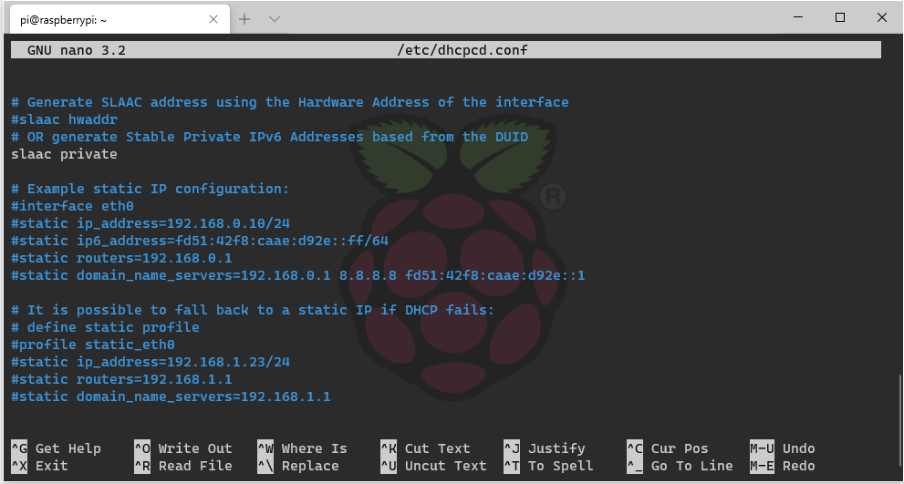
I’m going to set a static IP on my pi. To do this the file /etc/dhcpcd.conf must be edited. Scrolling to the bottom of the file commented out is a demonstration of how to set a static address.
For the USB interface I’e added two lines to the bottom of this file
interface usb0
static ip_address=10.11.12.13/24
After rebooting the Pi now shows this address for the USB network interface. I’m connecting to my pi with a Windows machine. After physically connecting the device a static IP address was set on the Windows side.
To ensure that things are working I started off trying to ping the device and received positive responses.
C:\Users\joel>ping 10.11.12.14

Pinging 10.11.12.14 with 32 bytes of data:
Reply from 10.11.12.14: bytes=32 time<1ms TTL=128
Reply from 10.11.12.14: bytes=32 time<1ms TTL=128
Reply from 10.11.12.14: bytes=32 time<1ms TTL=128
Reply from 10.11.12.14: bytes=32 time<1ms TTL=128
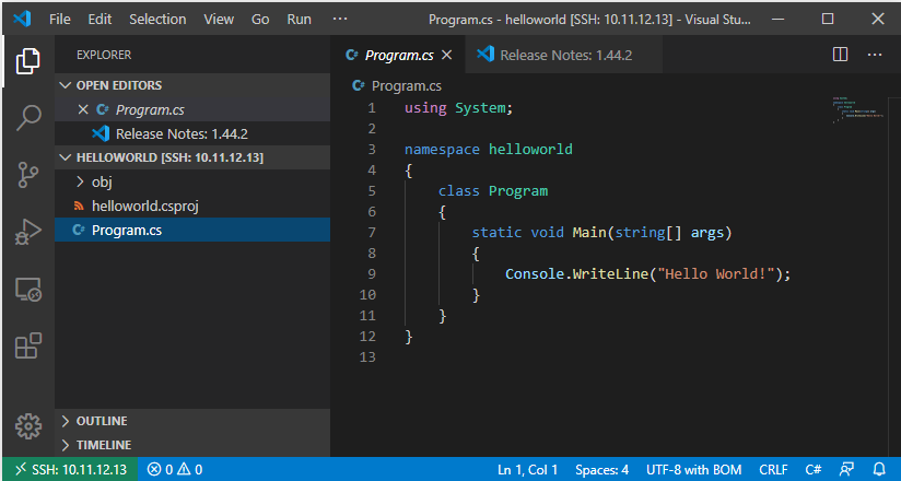
To try something a bit more functional I tried opening a folder on the Pi using Visual Studio Code running from my computer. Success!
In theory this could work with a phone or other mobile device. The restricting factor is whether someone’s mobile device allows changing settings on external network adapters. Many will allow communication over such adapters, but a much smaller set will allow you to change the settings.
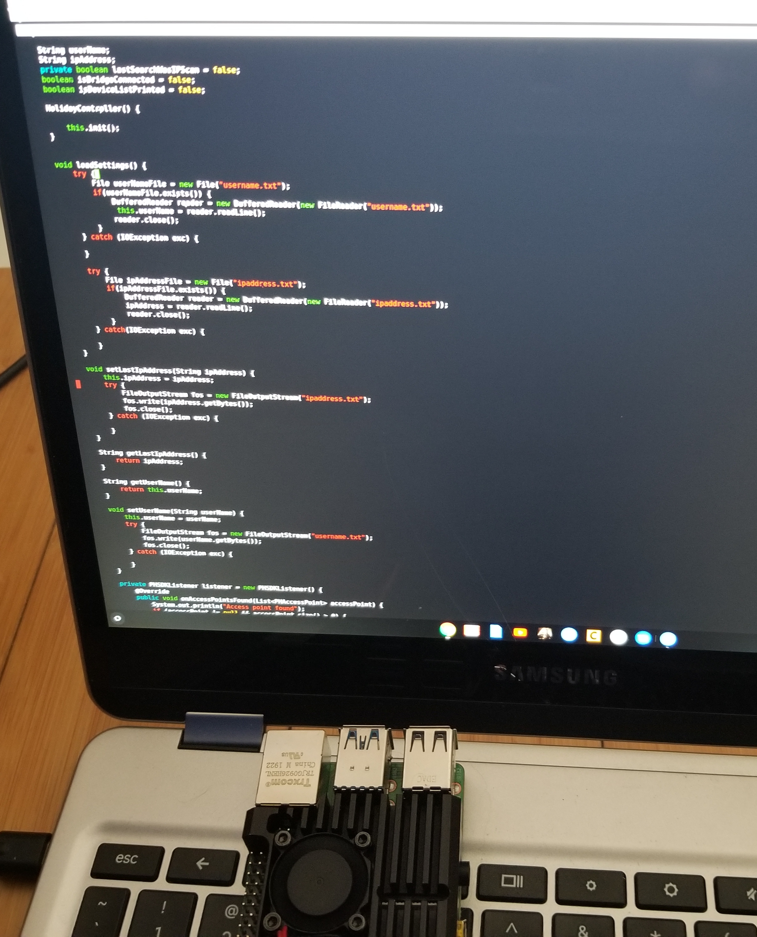
Editing a C# file on the Pi over SSH from a Chromebook
Something to note though, when using this solution on a mobile device there is a significant power drain, which makes sense; the mobile device’s battery is now working for two. There are a few ways to mitigate this but they break down to either batteries or external power. For batteries someone could add a battery to the Pi itself. There are a number of solutions that work well. I prefer PiJuice since it comes with some other options on invoking behaviours based power levels or time. Unfortunately at the time that I am writing this (during the 2020 shelter-at-home directive) this specific unit looks to be unavailable.
There are many other Pi batteries available. If you shop for one make sure that you purchase one that provides power through the headers or through pogo pens. Some provide power through the USB-C connector, which you need to keep available to act as a network connection. Also give consideration to the connector used to charge the unit you select. You might prefer micro-USB or USB-C. I would suggest not overclocking your Pi if it is running off of a battery. Some batteries might not be compatible with some types of cases. Ex: there is a Pi case that is essentially a heatsink that wraps the entire device. That would not work with with a power solution that uses pogo pens.
There have been a couple of SBC updates in the past few weeks that I thought were noteworthy.
The first is that there is now a 64-bit version of the Raspberry Pi operating system available. Previously if you wanted to run a 64-bit OS on the Pi your primary option was Ubuntu. Raspbian was 32-bit only. That’s not the case any more. The OS has also been rebranded as “Raspberry Pi OS.” Among other things with the updated OS a process can take advantage of more memory. Speaking of more memory, there is now also an 8 gig version of the Raspberry Pi 4 available for 75.00 USD.
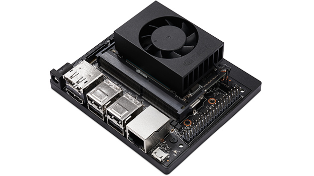
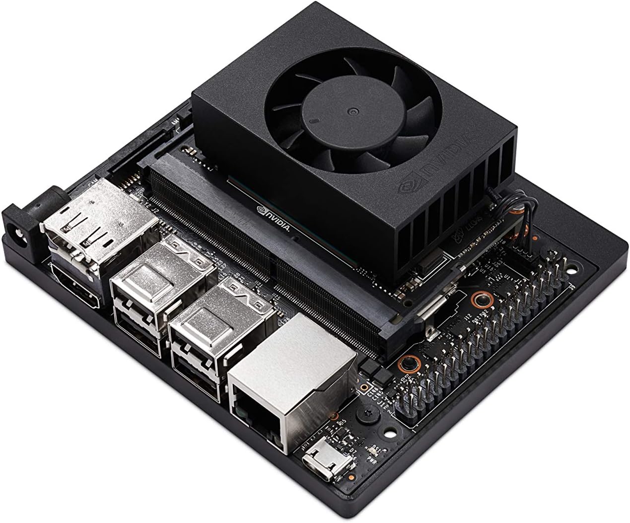
Jetson Xavier NX
Another family of single board computers is seeing an update. The Jetson family of SBCs has a new edition in the form of the Jetson Xavier NX. At first glance the Xavier NX is easily confused with the Jetson Nano. Unlike the Nano the Xavier NX comes with a WiFi card and a plastic base around the carrier board that houses the antenna. The carrier board is one of the variants that supports 2 Raspberry Pi camera connectors. The underside of the board now has a M.2 Key E connector. While it has a similar formfactor as the Jetson Nano a quick glance at the specs show that it is much more powerful.
Feature
Nano
Xavier NX
Core Count
4
6
CUDA Core Count
128
384
Memory
4 Gigs
8 Gigs
The Jetson Xavier NX is available now for about 400 USD from several suppliers.
Posts may contain products with affiliate links. When you make purchases using these links, we receive a small commission at no extra cost to you. Thank you for your support.
The .NET framework acts as an intermediate execution environment; with the right runtime a .Net executable that was made on one platform can run on another. With .NET Core the focus on the APIs that are supported on a variety of platforms allows it to be supported on even more platforms. Windows, Linux, and macOS are operating systems on which the .NET Core framework will run.
The .NET Core Framework also runs on ARM systems. It can be install on the Raspberry Pi. I’ve successfully installed the .NET CORE framework on the Raspberry Pi 3 and 4. Unfortunately it isn’t supported on the Raspberry Pi Zero; ARM7 is the minimum ARM version supported. The Pi Zero uses an ARM6 processor. Provided you have a supported system you can install the framework in a moderate amount of time. The instructions I use here assume that the Pi is accessed over SSH. To begin you must find the URL to the version of the framework that works on your device.
Visit https://dotnet.microsoft.com to find the downloads. The current version of the .NET Core framework is 3.1. The 3.1 downloads can be found here. For running and compiling applications the installation to use is for the .NET Core SDK. (I’ll visit the ASP.NET Core framework in the future). For the ARM processors there is a 32-bit and 64-bit download. If you are running Raspbian use the 32-bit version even if the target is the 64-bit Raspberry Pi; Raspbian is a 32-bit operating system. Since there is no 64-bit version yet the 32-bit .NET Core SDK installation is necessary. Clicking on the link will take you to a page where it will automatically download. Since I’m doing the installation over SSH I cancel the download and grab the direct download link. Once you have the link SSH into the Raspberry Pi.
You’ll need to download the framework. Using the wget command followed by the URL will result in the file being saved to storage.
After the download is completed it must be unpacked. The file location that I’ve chosen is based on the default location that some .NET Core related tools will look by default for the .NET Core framework. I am using the path /usr/share/dotnet. Create this folder and unpack the framework to this location.
sudo mkdir /usr/share/dotnet
sudo tar zxf dotnet-sdk-3.1.201-linux-arm.tar.gz -C /usr/share/dotnet
As a quick check to make sure it works go into the folder and try to run the executable named “dotnet.”
cd /usr/share/dotnet
./dotnet
The utility should print some usage information if the installation was successful. The folder should also be added to the PATH environment variable so that the utility is available regardless of the current folder. Another environment variable named DOTNET_ROOT will also be created to let other utilities know where the framework installation can be found. Open ~/.profiles for editing.
sudo nano ~/.profile
Scroll to the bottom of the file and add the following two lines.
Save the file and reboot. SSH back into the Pi and try running the command dotnet. You should get a response even if you are not in the /usr/share/dotnet folder.
With the framework installed new projects can be created and compiled on the Pi. To test the installation try making and compiling a “Hellow World!” program. Make a new folder in your home directory for the project.
mkdir ~/helloworld
cd ~/helloworld
Create a new console project with the dotnet command.
dotnet new console
A few new elements are added to the folder. If you view the file Program.cs the code has default to a hello world program. Compile the program with the dotnet command
dotnet build
After a few moments the compilation completes. The compiled file will be in ~/helloworld/Debug/netcoreapp31. A file name helloworld is in this folder. Type it’s name to see it run.
My interest in the .NET Core framework is on using the Pi as a low powered ASP.NET Web server. In the next post about the .NET Core Framework I’ll setup ASP.NET Core and will host a simple website.
To see my other post related to the Raspberry Pi click here.
The holiday season is upon us; by the end of this month I expect to start seeing my neighbors put out their fall decorations. By mid-October decorations for Halloween will show up. After Halloween the decorations roll back to fall themed only and then are changed to Christmas decorations right after new years. Two of these holidays tend to come with flashy displays and lights: Halloween and Christmas.
I primarily use Phillips Hue lighting throughout my house and it is a perfect companion for festive displays. The color bulbs are adaptable to any color scheme and the newly released Edison-style bulbs add a warm glow to fall scenes. The Phillips Hue lighting sets are programmable if you are using a hub. While the new light bulbs have Bluetooth support to directly be controlled by a phone there’s not public API for them (yet). For programming a hub is needed.
I’ve written on controlling the Phillips Hue lights before. Expanding on that I wanted to make a project that would let an IoT device trigger a scene according to some external event. I’ll use a motion sensor to trigger the relevant events.
But you could also use sound, change in temperature, lighting, or time as sources. I’ll be using a Raspberry Pi; it has network connectivity and can be easily interfaced to a number of devices. I’m using the Raspberry Pi zero but about any Pi will do. Hue does have available a motion sensor ; if one only wishes to control lights based on motion a solution is available. But if one wishes to have other triggers or trigger other actions along with the lights a custom solution is needed.
The Raspberry Pi 4 with a heat sink attached.
Raspberry Pi Zero with a 4-port USB hub
All that I want to happen is for the the lighting pattern to change when a person is detected. I’ll use a passive infrared sensor for presence detection. For Halloween I want a Hue light that is illuminating a jack-o-lantern to pulsate an orange color. When someone comes up knock on the door I want the light for the front door to go bright white. A few moments after a person is no longer there I want the system to go back to it’s previous pattern. But past a certain hour I don’t want this to continue; after 10:00pm the lights should extinguish. Simple enough, right?
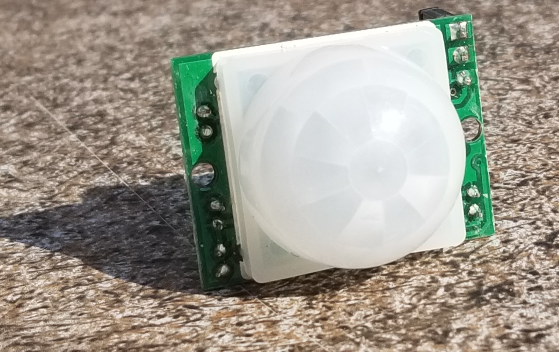
This is the passive infrared sensor that I used.
The physical build for this circuit is easy. The Passive Infrared Sensor (PIR) will get power from the VCC and ground pins of the Raspberry Pi. The signal line from the PIR can be connected to any of the GPIO pins. I’m going to use pin 3. The circuit will need to be put in an enclosure to protect it from rain or humidity in general. If your enclosure doesn’t already have a weather protected way to get power in your options are to either run the Pi off of a battery that is within the enclosure (that means periodic recharging) or drill a hole for the wires yourself and apply a sealant.
There are a lot of languages that I could use for writing my program on the Pi. Python, Java, and C/C++ make the top of the list (in no specific order). For this project I’ve decided to go with Java. To interact with the pins in Java we will need to import classes from com.pi4j.io and com.pi4j.wiringpi. These are not standard libraries; they exists to provide an interface to the pins. To demonstrate reading a pin in Java here is a simple program that will print text in a look that reflects the pin state.
import com.pi4j.io.*;
import com.pi4j.wiringpi.Gpio;
import com.pi4j.wiringpi.GpioUtil;

public class PinTest {
   public static void main(String args[]) throws InterruptedException {
      final GpioController gpio = GpioFactory.getInstance();
      Gpio.pinMode (3, Gpio.INPUT) ;
      while(true) {
         if (Gpio.digitalRead(3) == 0){
               System.out.println(The Pin is ON");
         }else{
            System.out.println("The Pin is OFF");
         }
      }
   }
}
Phillips has an SDK for Java. You might see it present as an SDK for Android, but it works fine in other Java environments. A convenience from this is that a significant portion of the development can be done on your computer of choice. I did most of the development on a Mac and used git to transfer it to the Raspberry Pi when done.
The color Hue lighting can take on a variety of colors.
The overall execution loop of the program will check whether or not the trigger condition has occurred. If the trigger condition has occurred then the program will activate a scene. If not then it deactivates the scene. The program loop also contains some debouncing logic. Depending on the type of sensor used and the sensors characteristics a sensor could change states with ever cycle. I’ve chosen to only deactivate if a certain amount of time has passed since the last activation. For initial development instead of interfacing to an actual sensor I have a method that is returning a random Boolean value. When the code is moved to the Raspberry Pi this method will be updated to read the state of the actual sensor. The following will only deactivate after there have been 2 seconds with no activation event.
Controlling the lights happens through the Hue SDK. Before activating the lights the Hue bridge must be discovered. While Hue makes a series of lights that have Bluetooth controllers built in and can be controlled without the Hue Bridge currently they only support APIs through the bridge. It is a required hardware component.
The SDK already contains functions for discovering the bridge. All that a developer needs to do is initiate a search and implement a callback object that will receive information on the bridges discovered. In the following I instantiate the Phillips Hue SDK object and register a listener. If the program had been connected with a bridge before the IP address if that bridge is loaded and it reconnects to it. Otherwise the search is initiated. As the search occurs the earlier registered listener receives callbacks.
private void init() {
    this.loadSettings();
    System.out.println("Getting SDK instance");
    phHueSDK = PHHueSDK.create();
    System.out.println("Setting App Name");
    phHueSDK.setAppName("HolidayLights");
    phHueSDK.setDeviceName("RaspPi");
    System.out.println("SDK initialized");
    phHueSDK.getNotificationManager().registerSDKListener(listener);

    if(this.getLastIpAddress()  != null) {
        System.out.println("Connect to last access point");
        PHAccessPoint lastAccessPoint = new PHAccessPoint();
        lastAccessPoint.setIpAddress(getLastIpAddress());
        lastAccessPoint.setUsername(getUserName());
        if (!phHueSDK.isAccessPointConnected(lastAccessPoint)) {
            phHueSDK.connect(lastAccessPoint);
        }
    } else {
        System.out.println("Searching for access point");
        PHBridgeSearchManager sm = (PHBridgeSearchManager) phHueSDK.getSDKService(PHHueSDK.SEARCH_BRIDGE);
        // Start the UPNP Searching of local bridges.
        sm.search(true, true);
    }
}
The listener is of type PHSDKListener. I won’t show the full implementation here but will show some of the more relevant parts.
When the bridges are found they are returned as a list. I’ve only got one on my home network and so I connect to the first one seen. If you have more than one bridge you’ll need to implement your own logic for making a selection.
@Override
public void onAccessPointsFound(List accessPoint) {
    System.out.println("Access point found");
    if (accessPoint != null && accessPoint.size() > 0) {
        System.out.println("Number of access points: "+new Integer(accessPoint.size()).toString());
        phHueSDK.getAccessPointsFound().clear();
        phHueSDK.getAccessPointsFound().addAll(accessPoint);
        phHueSDK.connect(accessPoint.get(0));
    }
}
When the connect attempt is made it is necessary to press the pairing button on the bridge. The console will print a message from the SDK saying this. Once the bridge is connected I save an instance of the bridge and the a
After the bridge connects the SDK will query the state of the lights on the system and update some objects representing the last known state of each light. The first time the cache is updated the program prints the name of each light and the light’s identity. This information is useful for selecting which lights will be controlled. The light list is saved for the program to use.
With that in place we now have enough information to change the state of the lights. To test things out I started with implementations of activateScene and deactivateScene that will just turn all the Hue lights on and off (don’t do this if you have other people in your dwelling that this would affect).
If the program is run at this point the lights will turn on and off somewhat randomly. Ultimately we don’t want it to control all the lights. Instead I want to be able to specify the lights that it is going to control. I’ve made a JSON file file that contains a couple of elements. One is the RGB color that I want to use in the form of an integer, the other is an array of numbers where each number is an ID for the light to be controlled. The RGB color is specified here as a base 10 number instead of the normal base 16 that you may see used for RGB codes. Unfortunately JSON doesn’t support hexadecimal numbers 🙁.
{
    "lights":[5, 7, 9],
    "color": 16711935
}
These values are read by the code. Before the code acts on any light it checks to see if its identifier is in this array before continuing. During activation if the identifier is in the array the light’s state is set to on, brightness is set to full, and the color is applied. The color must be converted to the right color space before being applied to the light; something that is done with a utility function that the SDK provides.
The last steps needed to make the device work as intended are to update the getActivationState() function to read the actual state of the motion sensor instead of a random value and wiring the motion sensor to a Raspberry Pi. From hereon the code is only going to work on a Raspberry Pi since the libraries for reading the pins are only applicable to this device. It is possible to dynamically load class libraries and use them as needed for the specific platform on which code is running. But information on doing that is beyond the scope of what I wish to discuss here.
I’m declaring a GpioController variable at the class level and am instantiating it in the constructor. I also set the mode of the IO pin that I’ll be using to input.
With that change it will now work. If the Raspberry Pi is placed in a position where the motion sensor has a view of the space of interest then it will control the lights. If you are using one of the earlier Raspberry Pis (anything before the Raspberry Pi 4) you should be able to also power the Pi off of a portable phone charger; there are many that will make sufficient batteries for the Pi. The Raspberry Pi 4 has higher energy requirements and you may run into more challenges finding a portable power supply that works.
Why use the Pi at all for this? Because there is a lot of room to expand. Such as using the video capabilities of the pi to power a display or controlling other devices. Controlling the lights is a start. I’ll be revisiting this project for add-ons in the future.
If you want to start on something similar yourself the following (affiliate) links will take you to the products on Amazon.
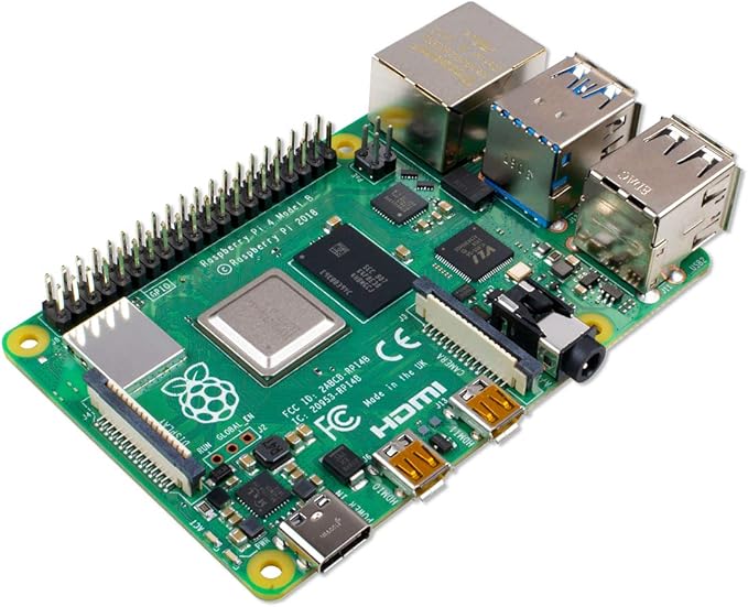
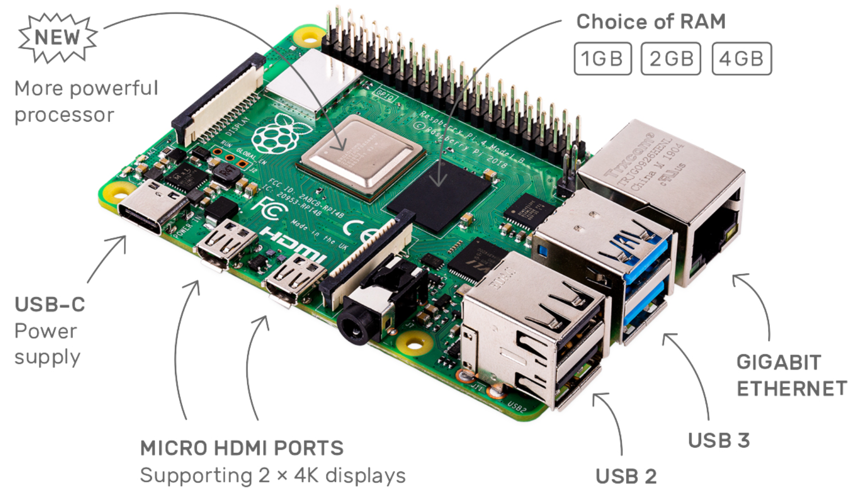
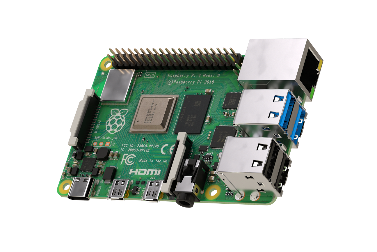
The fourth generation of the Raspberry Pi has been announced. Each generation of the Raspberry Pi is primarily identified by its specifications. (Not including the Raspberry Pi Compute module because it generally is not used by hobbyist). With the Raspberry Pi 4, this isn’t the case. There are three variations available. The new Raspberry Pi 4 comes with a 1.5 GHz ARM Cortex-A72 quad-core processor. With that processor the Raspberry Pi 4 can decode 4K video at 60 FPS or two 4K videos at 30 FPS. The amount of RAM available to the unit depends on the version. The smallest amount of RAM, 1 gig, is available for $35 USD. The next size, 2 gigs, can be purchased for $45 USD. The largest unit, 4 gigs, is $55 USD.
At first glance, the unit will be recognized as a Raspberry PI but a closer look at the ports will show some immediate differences. The Pi has converted from a micro-USB port to USB-C. The full sized HDMI port is gone and has been replaced with two micro-HDMI ports. The unit can drive two displays at once. A couple of the 4 USB ports have been upgraded to USB 3 while the other two are still USB 2. The wireless capabilities are upgraded to use USB 5.0 and dual-band 802.11ac Wi-Fi.
The unit is available for purchase from Raspberry Pi’s site now. A new case for the Pi 4 and a USB-C power supply of appropriate wattage are both available through the site as well.


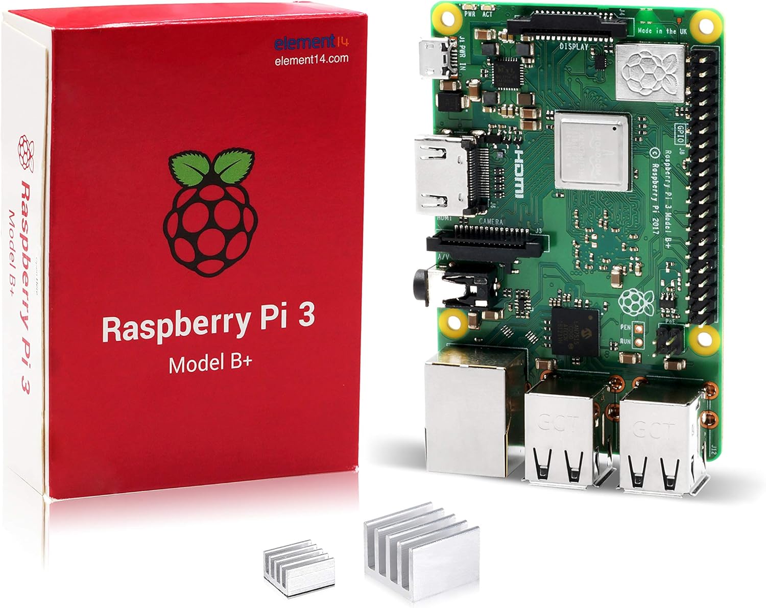

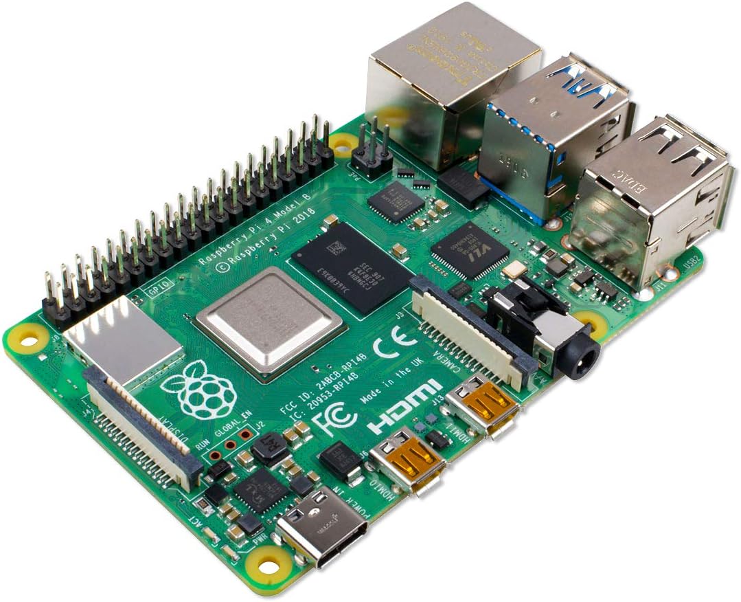 Raspberry Pi 4