I go through a lot more SD cards than a typical person. I’m usually putting these cards in single board computers like the Jetson Nano or the Raspberry Pi and am using them there. I have a lot of these devices. These cards only occasionally fail. But with a lot of devices “occasional” is frequent enough for my rate of card consumption to be higher than that of a typical consumer. The easy solution to this is to just not use SD cards. At this point, the Pi can boot of USB drives. I’ve generally resisted this for reasons of æsthetics. I just don’t like the U-shapped USB connector (feel free to tell me how silly that is in the comments section).
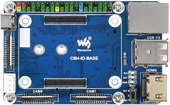
Enter the Raspberry Pi CM4. These modules have a PCIe interface, and you can select the board that has the hardware that you need. One of those boards is the WaveShare CM4-IO-Base. Among other hardware, this board has a PCIe M.2 keyed slot. There are two versions of this board, version A and version B. The main difference between these is the model B has a real time clock while the model A does not. Otherwise, these boards can be treated as identical
The CM4-IO-BASE has screw holes in positions that are identical to what one would expect for a Raspberry Pi 4B. This makes it compatible with a number of bases on which you might want to attach the board. It does differ from the Pi 4B in that it uses a full-sized HDMI port placed where two of the USB ports are on the Pi 4B. At first glance, it appears to give you less USB and HDMI options than the Pi 4B. But two USB connections and an HDMI connection is available from the underside of the board. You would need to purchase the HDMI+USB Adapter to use those or interface to them directly.

The top of the board has two connectors for cameras, and a connector for an external display. The feature of interest to me was the M.2 PCIe interface on the underside of the board. I decided on a M.2 2242 drive with 256 Gigs of capacity. I’ve seen drives of this size up to 2-terabytes in size (for significantly more).

Getting the Pi to bootup from the NVME isn’t hard. The Compute Module that I have has eMMC memory; that’s basically like having an SD card that you can’t remove. Getting the Pi to boot from the NVME drive involves writing the Pi OS to the MVNE drive and changing the boot order on the Pi. For changing the boot order on the Pi I needed another Linux device. I used another Raspberry Pi.
Writing the image to the NVME drive works in the same way that you would write the image to any other SD card. I happen to have some external NVME drive enclosures removed the drive from one of them and placed my Pi’s NCME drive in it. The Raspberry Pi Imager accepted the drive as a target and wrote the OS to it. The tricky part was modifying the boot order on the CM4.

The default boot order on the CM4 is 0xF461. This is something that didn’t make sense to me the first time that I saw it. The boot order is a numeric value that is best expressed as a hex number. Each digit within that number specifies a boot device. The Pi will start with the boot device that is specified in the lowest hex digit and try it first, and then go to the next hex digit.
| Digit | Device |
| 0x1 | SD |
| 0x2 | Network |
| 0x3 | RPI Boot |
| 0x4 | USB Mass Storage |
| 0x5 | CM4 USB-C Storage Device |
| 0x6 | NVME Drive |
| 0xE | Stop/Halt |
| 0xF | Reboot |
For the boot order 0xF461 the Pi will try to boot to devices in the following order.
- 0x1 – Boot from the SD Card/eMMC
- 0x6 – Boot from the NVME drive
- 0x4 – Boot from a USB mass storage device
- 0xF – Reboot the pi and try again.
If you have a CM4 with no memory, this means that all you need to do to ensure that the right boot order is followed is to ensure that you don’t have an SD card connected to the board. You are ready to boot from the NVME drive. That’s not my scenario, I had more work to do. I updated the boot order alongside the Pi’s firmware. The CM4 is usually in one of two modes. It is either running normally, in which case the boot loader is locked, or it is in RPI Boot mode, in which case the bootloader can be written to, but the OS isn’t running. The CM4 cannot update its own bootloader. To update the bootloader, another computer is needed. I think that the best option for updating the boot loader is another Linux machine. In my case, I chose another Raspberry Pi.
The Raspberry Pi can already b picky about the power supplies that it works with. I used a USB-C power supply from a Raspberry Pi 400 (the unit built into the keyboard) for the following steps. The usual power supply that I used with my Pi wasn’t sufficient for powering 2 Pis. You’ll find out why it needed to work for 2 Pis in a moment. I used a Raspberry Pi 4B for writting the firmware to the CM4. To avoid confusion, I’m going to refer to these two devices as Programmer Device and the CM4.
On the CM4-IO-BASE board there is a switch or a jumper (depending on hardware revision) for switching the Pi to RPI Boot Mode. Set a jumper on this pin or turn the switch to “ON”. Connect the CM4 to the Programmer Device with a USB-A to USB-C cable. From the programmer device, you will need to replicate a GitHub repository that has all of the code that you need. Open a terminal on the Programmer Device, navigate to a folder in which you want to replicate the code, and use the following commands to clone and build the code.
git clone https://github.com/raspberrypi/usbboot --depth=1
cd usbboot
make
The code is now downloaded or built. Enter the recovery folder and edit the file named boot.conf to change the boot order.
cd recovery
nano boot.conf
At the time of this writing, that file looks like the following.
[all]
BOOT_UART=0
WAKE_ON_GPIO=1
POWER_OFF_ON_HALT=0

# Try SD first (1), followed by, USB PCIe, NVMe PCIe, USB SoC XHCI then network
BOOT_ORDER=0xf25641

# Set to 0 to prevent bootloader updates from USB/Network boot
# For remote units EEPROM hardware write protection should be used.
ENABLE_SELF_UPDATE=1
The line of interest is BOOT_ORDER=0xf25641. The comment in this file already lets you know how to interpret this line. You want the NVME drive (0x6) to be the first drive. To make that happen, the digit 6 needs to be the last digit. Change it to 0xf25416. With this change, the CM4 will try to boot from the NVME first and the eMMC second. IF you ever want to switch back to using the eMMC you only need to remove the NVME drive. There is a file named pieeprom.original.bin. This is going to be written to the CM4. To ensure that the CM4 has the latest [stable] firmware, downloaded the latest version from https://github.com/raspberrypi/rpi-eeprom/tree/master/firmware/stable and overwrite this file. Looking in that folder right now, I see the most recent file is only 15 hours old and named pieeprom-2022-02-10.bin. To download this from the terminal, use the following command.
wget https://github.com/raspberrypi/rpi-eeprom/raw/master/firmware/stable/pieeprom-2022-03-10.bin -O pieeprom.original.bin
After the file is downloaded, run the update script to assemble the new firmware image.
./update-pieeprom.sh
Navigate to the parent folder. Run the rpiboot utility with the recovery option to write the firmware to the device.
sudo ./rpiboot -d recovery
This command should only take a few seconds to run. When it is done you should see a green light blinking on the Pi signaling that it has updated its EEPROM. Disconnect the CM4 from the Programmer Device. Remove the jumper or set the RPI Boot switch to off. Connect the Pi to a display and power supply. You should for a brief moment see a message that the Pi is expanding the drive partition. After the device reboots it will be running from the NVME.
At this point my primary motivation for using the CM4-IO-BASE-B board has been achieved. But there is some additional hardware to consider. If you have the CM4-IO-BASE model B then there is a real time clock to setup. For both models, there is fan control available for setup.
Real Time Clock Setup
The real time clock interfaces with the Pi via I2C. Ensure that I2C is enabled on your Pi by altering the file boot/config.txt.
sudo nano /boot/config.txt
Find the line of the file that contains dtparam=audio=on and comment it out by placing a # at the beginning of the line. Add the following line to config.txt to ensure I2C is enabled.
dtparam=i2c_vc=on
Reboot the device. With I2C enabled you can now interact with the RTC through code. Waveshare provides sample code for reading and writing from the clock. The code in its default state is a good starting point, but not itself adequate for setting the clock. The code is provided for both the C language and Python. I’ll bu using the C-language version of the code. To download the code, use the following commands.
sudo apt-get install p7zip-full
sudo wget https://www.waveshare.com/w/upload/4/42/PCF85063_code.7z
7z x PCF85063_code.7z -O./
cd PCF85063_code
After downloading the code, enter the directory for the c-language project and build and run it using the following commands.
cd c
sudo make clean
sudo make -j 8
sudo ./main
You’ll see the output from the clock. Note that the clock starts from just before midnight of February 28, 2021 and progresses into March 1. The code has the starting date hard coded. Let’s look at the code in main.c to see what it is doing.
#include <stdio.h>		//printf()
#include <stdlib.h>		//exit()
#include <signal.h>     //signal()

#include "DEV_Config.h"
#include <time.h>
#include "waveshare_PCF85063.h"

void  PCF85063_Handler(int signo)
{
    //System Exit
    printf("\r\nHandler:exit\r\n");
    DEV_ModuleExit();

    exit(0);
}

int main(void)
{
	int count = 0;
	// Exception handling:ctrl + c
    signal(SIGINT, PCF85063_Handler);
    DEV_ModuleInit();
    DEV_I2C_Init(PCF85063_ADDRESS);
	PCF85063_init();

	PCF85063_SetTime_YMD(21,2,28);
	PCF85063_SetTime_HMS(23,59,58);
	while(1)
	{
		Time_data T;
		T = PCF85063_GetTime();
		printf("%d-%d-%d %d:%d:%d\r\n",T.years,T.months,T.days,T.hours,T.minutes,T.seconds);
		count+=1;
		DEV_Delay_ms(1000);
		if(count>6)
		break;
	}

	//System Exit
	DEV_ModuleExit();
	return 0;
}
You can see where the time is set with the functions PCF85063_SetTime_YMD and PCF85063_SetTime_HMS. Let’s update this to use the date/time that the system is using. Place the following two lines above those two functions. This will only grab the system time and print it.
    time_t T = time(NULL);
    struct tm tm = *localtime(&T);

    printf("***System Date is: %02d/%02d/%04d***\n", tm.tm_mday, tm.tm_mon + 1, tm.tm_year + 1900);
    printf("***System Time is: %02d:%02d:%02d***\n", tm.tm_hour, tm.tm_min, tm.tm_sec);
Build and run the program again by typing the following two lines from the terminal.
sudo make -j 8
sudo ./main
This time the program will print the actual current date and time.
USE_DEV_LIB
Current environment: Debian
DEV I2C Device
DEV I2C Device
***System Date is: 20/03/2022***
***System Time is: 19:19:06***
21-2-28 23:59:58
21-2-28 23:59:59
21-3-1 0:0:0
21-3-1 0:0:1
21-3-1 0:0:2
21-3-1 0:0:3
21-3-1 0:0:4
Let’s pass in this information to the calls that set the date and set the time. The information that we need is in the tm structure. Note that in this structure the first month of the year is associated with the value 0. Also note that the tm structure stores the year as the number of years since 1900, while the RTC stores the year as the number of years since 2000. We need to shift the value by 100 to account for this difference. The updated lines of code look like the following.
    printf("***System Date is: %02d/%02d/%04d***\n", tm.tm_mday, tm.tm_mon + 1, tm.tm_year + 1900);
    printf("***System Time is: %02d:%02d:%02d***\n", tm.tm_hour, tm.tm_min, tm.tm_sec);
	PCF85063_SetTime_YMD(tm.tm_year - 100,tm.tm_mon + 1,tm.tm_mday);
	PCF85063_SetTime_HMS(tm.tm_hour,tm.tm_min,tm.tm_sec);
When you run the program again, you’ll see the current time. But how do we know the RTC is really retaining the time? One way is to run the program again with the calls that set the time commented out. One would expect the RTC to continue to show the real time based on the previous call. I tried this, and the RTC was printing out times from 01-01-01. Why did this happen?
I’ve not completely dissected the code, but I did fine that a call to PCF85063_init() at the beginning of main resets the clock. I just commented this out. With that call not being made, the time is retained. I use this call when setting the clock though. I’ve altered the program to accept a command line parameter. If setrtc is passed to the program as a command line argument it will set the time on the RTC. If setsystem is passed as the parameter then the program will attempt to set the system time. Setting the system time requires root privileges. If you try to set the time with this program without running as root then the attempt will fail.
The final version of this code is available in my GitHub account. You can find it here.
Fan Control
There’s a difference in the version A and version B for the fan control. On version A the fan is connected to port 18. It can be turned on and off by changing the state of this pin. For version B the fan is controlled through the I2C bus. Example code is also provided for fan control on version B. To download the fan code for version-B use the following commands from the terminal.
sudo apt-get install p7zip-full
sudo wget https://www.waveshare.com/w/upload/5/56/EMC2301_code.7z
7z x EMC2301_code.7z -O./
cd EMC2301_code
To build the code, use the following commands.
cd c
sudo make clean
sudo make -j 8
sudo ./main
Let’s look at a highly abridged version of the code.
		EMC2301_start();
	/*********************************/
		EMC2301_setSpinUpDrive(60);
		EMC2301_setSpinUpTime(300);
		EMC2301_setDriveUpdatePeriod(100);
		EMC2301_RPMEnable();

		EMC2301_writeTachoTarget(8192);
		for(int i=0;i<10;i++)
		{
			EMC2301_fetchFanSpeed();
			DEV_Delay_ms(500);
		}
Fan control is straight forward. After some setup calls, the fan speed can be set by writing to EMC2301_writeTachoTarget(). The call to EMC2301_fetchFanSpeed() will read the current fan speed. Through repeated calls to this function you can see the acceleration of the fan when the speed is changed.
Other Hardware
Take note that a number of interfaces are disabled by default on the CM4. This includes the USB-C, the two DSI camera ports, and the display connector. If you need to use any of these, the resources page for this board has the information that needs to be added to the
Conclusion
Pi setup for this board was pretty easy. I’d definitely consider getting another one. If I had to do things all over again though I would double-check my cables. There was a moment when I thought things were not working because I wasn’t getting a video signal. It turns out that I had two HDMI cables close to each other that I thought was a single cable. I didn’t get a video signal because I had connected to a cable that was not terminating at my display (time to consider cable organization). This is a great board if you need a Pi that is close to the usual form factor but with more memory. I might consider another if I can acquire another CM4 (which is difficult in this chip shortage).
Resources
Posts may contain products with affiliate links. When you make purchases using these links, we receive a small commission at no extra cost to you. Thank you for your support.
Twitter: @j2inet
Instagram: @j2inet
Facebook: j2inet
YouTube: j2inet
Telegram: j2inet