Photography and Holography, A Brief History
I was having a discussion about some recent articles from a few blogs. The articles were speaking of what they labeled as holograms. But some of the articles didn’t actually have anything to do with holography despite their stated subjects. The question came up “What is a hologram.” I think the answer to that question can be better understood by contrasting it against photography and a brief presentation of the differences of the principals of the two technologies.
Development of Photography and Optics
As with many technologies the contributions that led to photography were developed by incremental discovers and developments over a long period of time. Principals of photography were developed well before those of holography. One of the earliest devices related to photography was the camera obscura (Latin, camera meaning chamber or room, obscura meaning dark). When we think of cameras now we typically don’t think of rooms in a building. The usage of many words change over time and our usage of the word camera today evolved from this usage. A camera obscura can refer to a room or a box with light blocked off except for a single hole through which light is allowed to enter. An upside down image of the scene outside the room is projected on the wall to the opposite of the hole. The earliest known writings that mention such a device are found in the writings of the philosopher Mozi. Mozi asserted from the camera obscura that light travels in a straight line. His followers developed an optic theory based on this.
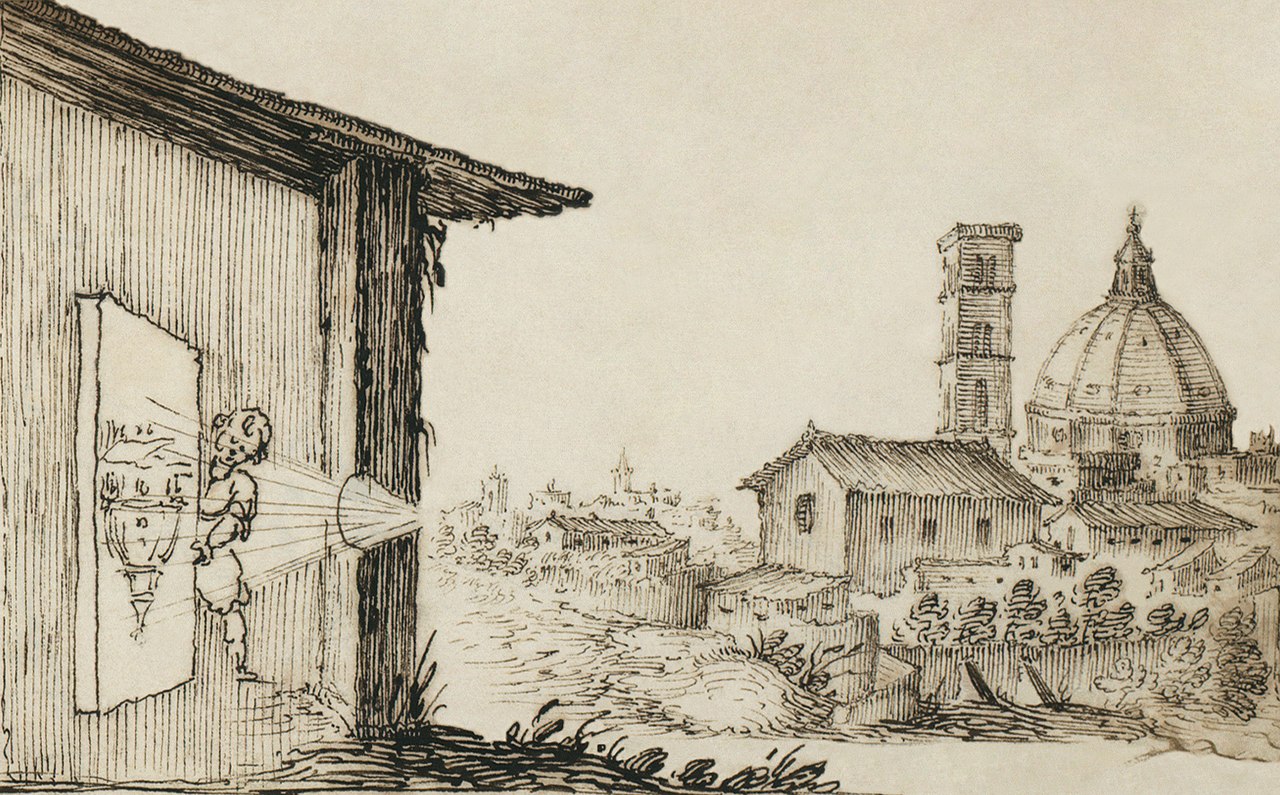
Image Credits: Wikipedia
There had been two prevailing theories of how vision worked. The emissions theory of vision hypothesized that the eyes emitted something and that we were able to see these emissions had to collide with the object being perceived. It was supported by people such as Ptolemy and Euclid The intromission theory of vision (supported by Aristotle) hypothesized that physical forms of the object were entering one’s eye. Around 1011 – 1020 C.E. the “Book of Optics” was written by Alhazen. His was that from an illuminated object light of different colors would travel from the object in every direction. Thought experiments with lenses and mirrors he developed a more complete theory on how light travels. He could not answer the question of how that light formed an image on an eye. Kerplar addressed the question of how images form. Kerplar also saw the human mind as playing an active role in the perception of images.
It had already been known that exposure to light would change the color of certain substances. During the year 1727 in German Johann Heinrich Schulze published the results of experiments that showed that the darkening of silver salts was due to exposure to light. The first person to capture images with through such a process was Thomas Wedgwood. But his images were less than permanent as they would fade with further exposure to light. It wasn’t until 1826 that Joseph Nicéphore was able to create the first permanent image. He used a camera obscura with a eight hour exposure time through a process he called heliography (Greek, helio from sun and -graphy from writing/message. Joseph Nicéphore partnered with Louis-Jacques-Mande Daguerre to improve the process and carried on with the work on improving the contrast after Nicéphore’s death. Henry Fox Talbot had independently developed a process for fixing silver salts only to find that Daguerre had accomplished this before him. Nevertheless he sent a paper to the Royal Institution titled “Some Account of the Art of Photogenic Drawing.” In his process a negative image was captured and that negative image was later copied to a positive image. By contrast for the daguerreotypes direct images were created. The images from daguerreotypes were sharper, but the production of the negative for Talbot’s two step process allowed unlimited positive images to be produced from the negative. The first daguerreotypes camera was produced in 1839.

Image Credits: Wikipedia
With the process improvements instead of an exposure that lasted for hours in a dark room exposures took minutes for a portable box. Instead of a shutter a lens cap was removed from the front of the device. As film became more sensitive exposure times were reduced from minutes to seconds. A mechanical shutter was added to better control exposure times. In 1885 George Eastman started producing paper film. By 1889 he changed to using celluloid film. Eastman decided to sell cameras at a loss expecting to make money back from the sales of film. The first camera was called the “Kodak.” In 1975 Kodak engineer Steven Sassonmade a camera with an electronic sensor. The images were captured at a resolution of 0.1 megapixel. He also combined the sensor with parts from a movie camera to save series of images to a cassette tape that could be viewed on a TV monitor. Twenty five years later flash memory started to replace the use of film and magnetic.
Beginning of 3D Imaging
The same year that the first daguerreotype camera was produced Sir Charles Wheatstone invented the reflecting mirror stereoscope. He used mirrors at 45-degrees to to the viewer’s eyes so that each eye would see a slightly different drawing. Through binocular depth perception the two images were experienced by the person as a single three dimensional scene.
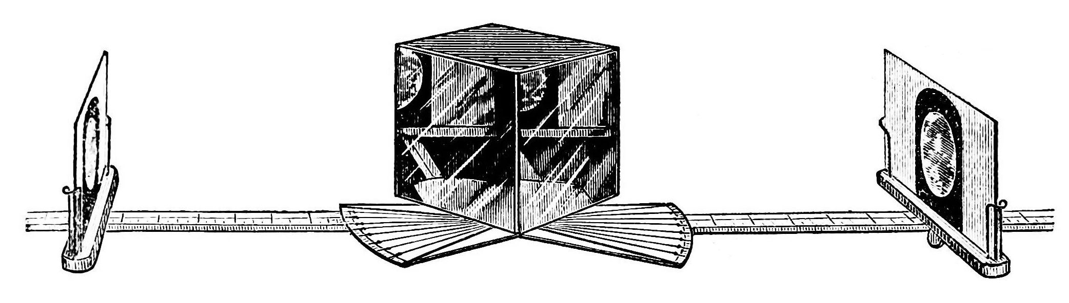
Image Credits: Wikimedia
The same year David Brewster created a simple stereoscope crediting the idea to a teacher of mathematics named Elliot that is said to have come up with the idea in 1823. Brewster improved upon the stereoscope concept with the lenticular (lens based ) stereoscope (also known as the Brewster Stereoscopes). Taking the design to France improvements were made on the stereoscope by Jules Duboscq with the creation of the stereoscopic daguerreotypes. In 1861 Oliver Wendell Holmes made a verion of the stereoscope that was easier to produce. Patend in 1939 was the View-Master Stereoscope. In 1950 a device titled the “Sensorama” was created designed to present stereoscopic motion pictures, smells, feelings, and sound. About the same time Douglas Engelbart (inventor of the mouse) was experimenting with using screens as input and output devices. In 1968 the first system that would be describe in modern terminology as “augmented reality” was created by Ivan Sutherland and Bob Sproull. It was heavy and the headset had to be suspended from the ceiling. The graphics it displayed were wire frames.
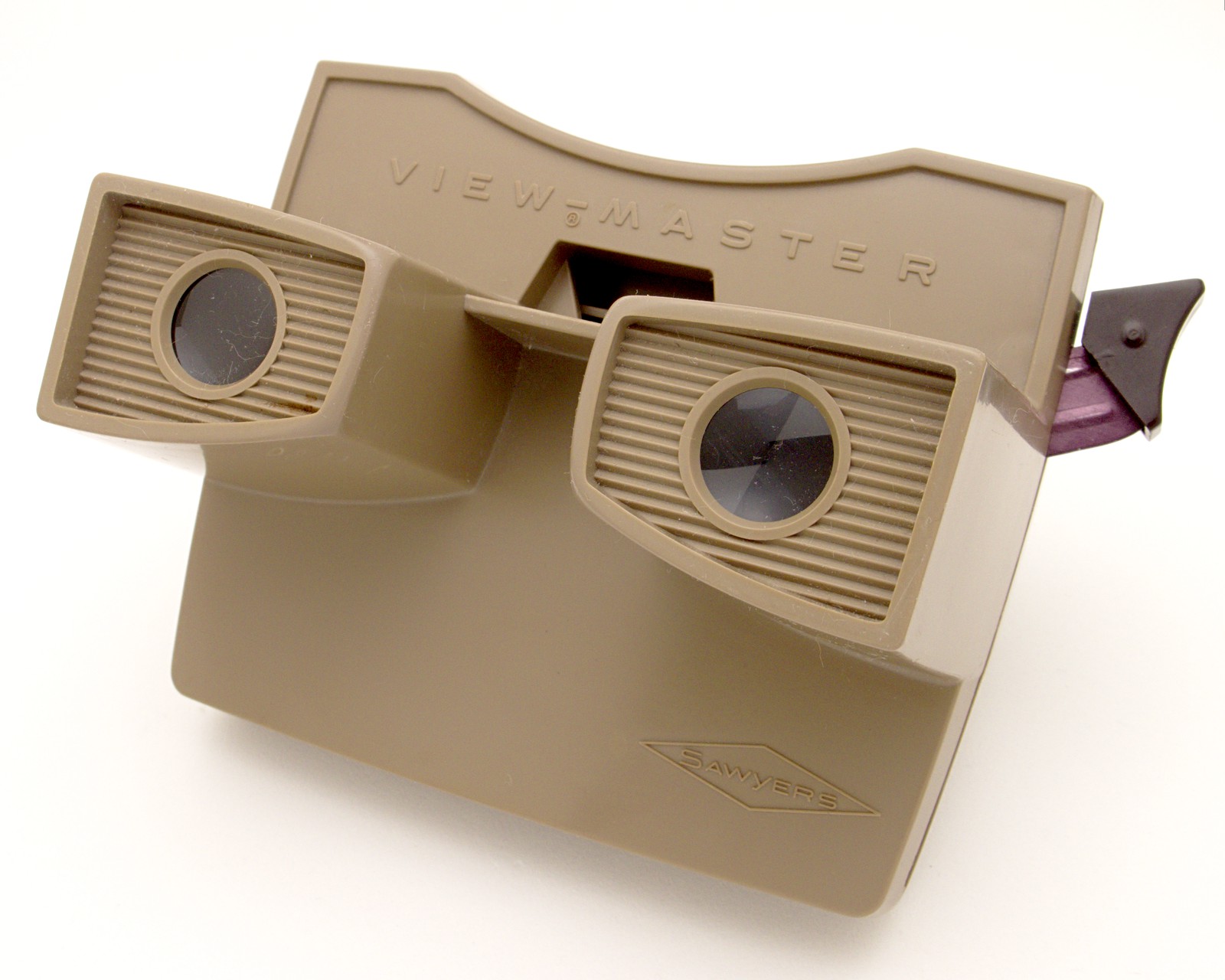
View Master Image Credits:Wikimedia

Holmes Stereoscope Image Credits: Wikimedia
Development of Holograms
The development of holograms occurred much more recently in history. In 1947 Dennis Gabor developed holographic theory. His efforts were to improve the quality of images from electron microscopes. In electron holography a subject is placed in a diverging electron beam (This would be a good place to talk about Quantum coherence, or it may be bad to talk about it at all).. Electrons that are scattered by the object and electrons undisturbed by the object both strike a detector and create an interference pattern with each other. An image of the object is constructed by this interference pattern. Holograms made with light didn’t occur at the time in part because of the properties of available light sources. Many light sources emit light that falls across a spectrum of wavelengths (colors) and are not a single pure color. It wasn’t until 1960 that such a light source became available through the work of N. Bassov and A. Prokhorov, and Charles Towns with the development of the laser. Light emitted from a laser has two important properties that are vital to making holograms. The light is monochromatic (a single pure color) and the light is coherent. One might wonder if single color light is needed why not add a color filter to a light bulb. Most light filters will reduce but not necessarily completely eliminate the other wavelengths of light. It’s also not coherent. (note: LED lighting achieves being monochromatic without being coherent).
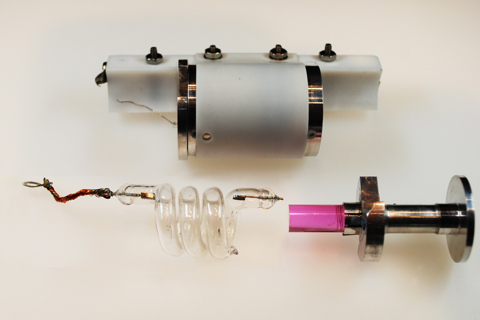
Components of original Ruby Laser. Image credits Wikimedia.
I really don’t like this explanation. I need to work on this Understanding light coherence requires a bit of knowledge of the wave-particle duality of light. Those that performed the double-slit experiement in a physics class may remember discussing this. Consider ripples on the surface of water from a pebble being dropped in. If you could view a cross section of one of the waves you’ll see the ripples form crests and troughs. If two pebbles are dropped in close to each other at the same time waves will emanate from two spots and overlap and interfere with each other. There will be areas where two crests coincide together forming an even higher crest (constructive interference). There will be areas where two troughs coincide forming a lower trough (constructive interference). And there will be areas where a trough from one wave and a crest from the other coincide resulting in the water being at the same level it was at before there were any waves (destructive interference). The distance between corresponding parts of the wave (ex: from one crest to another) is the “wave length.” The number of crests or troughs that occur over some period of time is the wave frequency. This same principal occurs with sound waves. Noise cancelling headphones use destructive interference to reduce the intensity of the sound-waves reaching the ears of those wearing them. The same principal is also applicable to light. Most normal light sources
One process for producing light holograms is similar to that of electron holography. Instead of using a detector being hit with undisturbed and scattered electrons a detector is hit with undisturbed and scattered particles of light (photons). The detector is a holographic plate. Because slight movement of the subject being holographed, the light source and optics, or the holographic plate would change the interference pattern it’s necessary for all of these parts to be absolutely still when the “image” is being made. After the exposure of the holographic plate it can be fixed/developed so that further exposure to light won’t damage recording.
Looking at an object through a hologram is like looking at an object through a window. If you took a hologram and broke it in half it doesn’t prevent you from being able to see the hologram. It’s analogous to reducing the size of the window through which could look by painting over part of it. While you can still see outside the number of angles from which you can view the scene is reduced. If you move your head to the left or right your perspective of the objects holographed will change which contributes to the perception of depth. Each observer of a hologram will see it from her own perspective. Each eye having it’s own perspective provides the stereoscopic depth queue.
Is it Really a Hologram
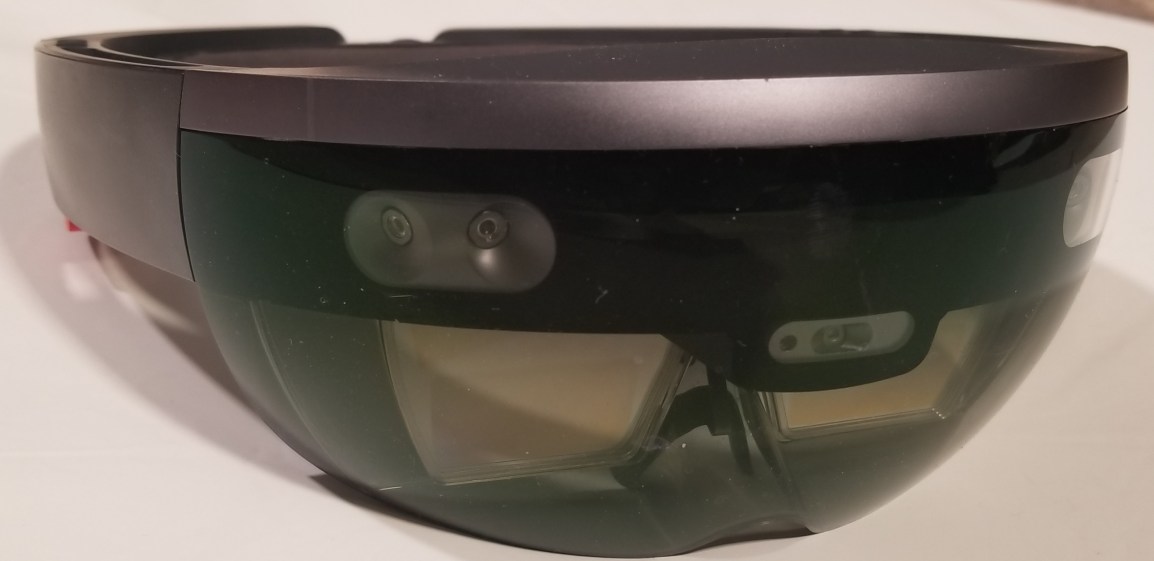
Returning to the discussion that inspired this entire post, when I was commenting on an article I was surprised that the article that mentioned holograms in it’s title was actually about holograms. Most articles I’ve come across mentioning holograms are not about holograms. What about the Hololens? It is described as being “the first fully untethered, holographic computer, enabling you to interact with high‑definition holograms in your world.” Are these really holograms? No, they are not holograms in the same sense as the word is used in holography. Computer based systems are full of terms and names that have been borrowed from other items and concepts. We often use these terms without thinking much about them. An audio streaming application isn’t really a radio. The root graphical interface on my computer isn’t really a desktop. There’s a long tradition of adopting terms as a metaphor. After those terms are used long enough they they come to denote the item for which they have been used. Internet radio isn’t radio, but it may have some of the experience of using a radio. The root graphical interface of some computers has been called the “Desktop” for 34 years at the time that I”m writing this. Similarly the images viewed through the Hololens are not from holography. But there are elements of the experience of viewing a hologram that one has with the Hololens. If you move your head from left to right the perspective of the object changes. There are several perceptual depth queues experiences including the images being stereoscopic, parallax, and perspective transformations of the object represented. The use of the word seems to communicate well what to expect from the experience; the presence of an image with depth.
