NVIDIA is holding a session on an introduction to Edge Computing. The introduction is said to cover fundamentals, how to integrate edge computing to your infrastructure, which applications are best deployed to the edge, and time for Q&A. The conference is at no cost. If you’d like to register for the conference, use this link.
Posts may contain products with affiliate links. When you make purchases using these links, we receive a small commission at no extra cost to you. Thank you for your support.
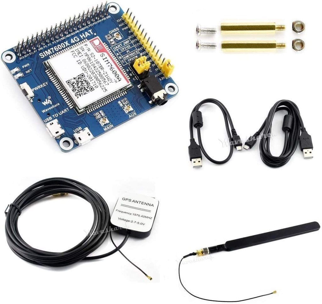
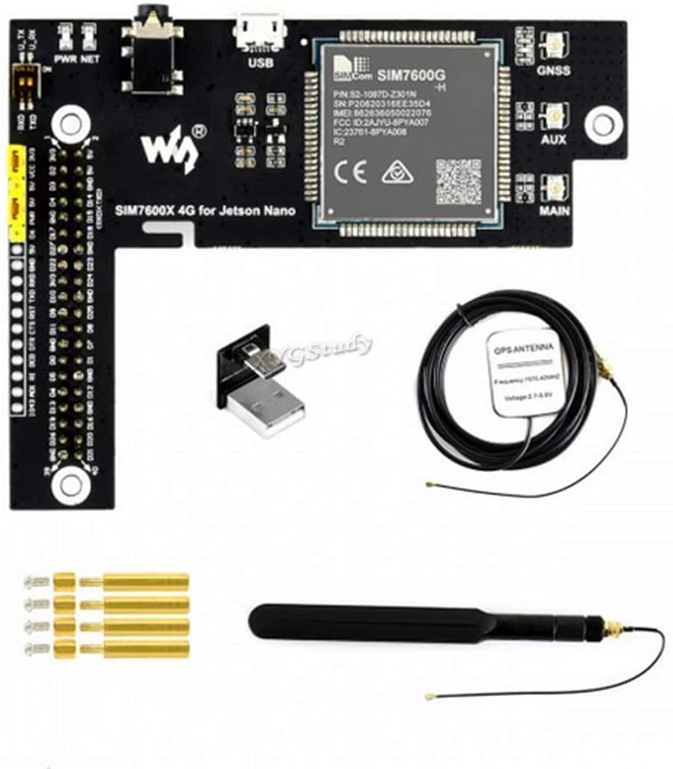
I’ve been using the Waveshare 7600 4G for the Jetson Nano (hereon referred to simply as the 7600). It gives the Jetson a connection for 4G mobile networks, GPS, and the ability to make and receive phone calls and SMS. (If you are looking for information on getting a WiFi connection see this post.) The Waveshare 7600 4G is a board built around the SIMCOM SIM7600X, an integrated circuit for providing communications functionality for a mobile phone. Waveshare makes variations of this device for both the Raspberry Pi and the Jetson Nano. While there is a wide amount of overlap in the usage of both devices, there are differences that are not immediately apparent from the top-level documentation. That said, reading documentation on one gives insight in using the other. The pin assignments used differ, but most of usage and functionality are the same.
When I initially looked at the Waveshare 7600 4G for the Jetson, there were elements of usage that didn’t make sense to me without consulting documentation from the chip maker and the schematic provided by Waveshare.
You don’t need to be familiar with the electrical schematic for the Waveshare board to use it. But if you would like more insight as to what the board is doing, continue reading.
SIMCOM 7600 Pinout
A quick glance of the pinout for the SIMCOM 7600 integrated circuit gives hints at a number of interfaces the chip supports. There are pins for power control, USB data transfer, interfacing to an SD card, GNSS, Flight mode, I2C, a UART interface, functionality concerning batteries, and analog to digital conversion. While the SIMCOM 7600 supports all of these interfaces, the Waveshare 7600 board built around this supports a subset of these interfaces; some of the lines on the SIMCOM 7600 are not connected to an external interface.
The schmatic that Waveshare provides is available on their Wiki at this URL. In the center of the schematic is the SIM7600.
SIM7600CX
Looking at this part of the diagram alone, you might notice that the pins labeled SCL and SDA are both tied to the positive voltage source instead of to other circuitry. These labels are associated with an I2C interface. Since the Waveshare’s board does not bridge the I2C pins between the Jetson Nano and the SIMCOM 760X, there is no I2C that you can use. Let’s take a look at how Waveshare’s device is connected to the Jetson Nano’s 40 pin header.
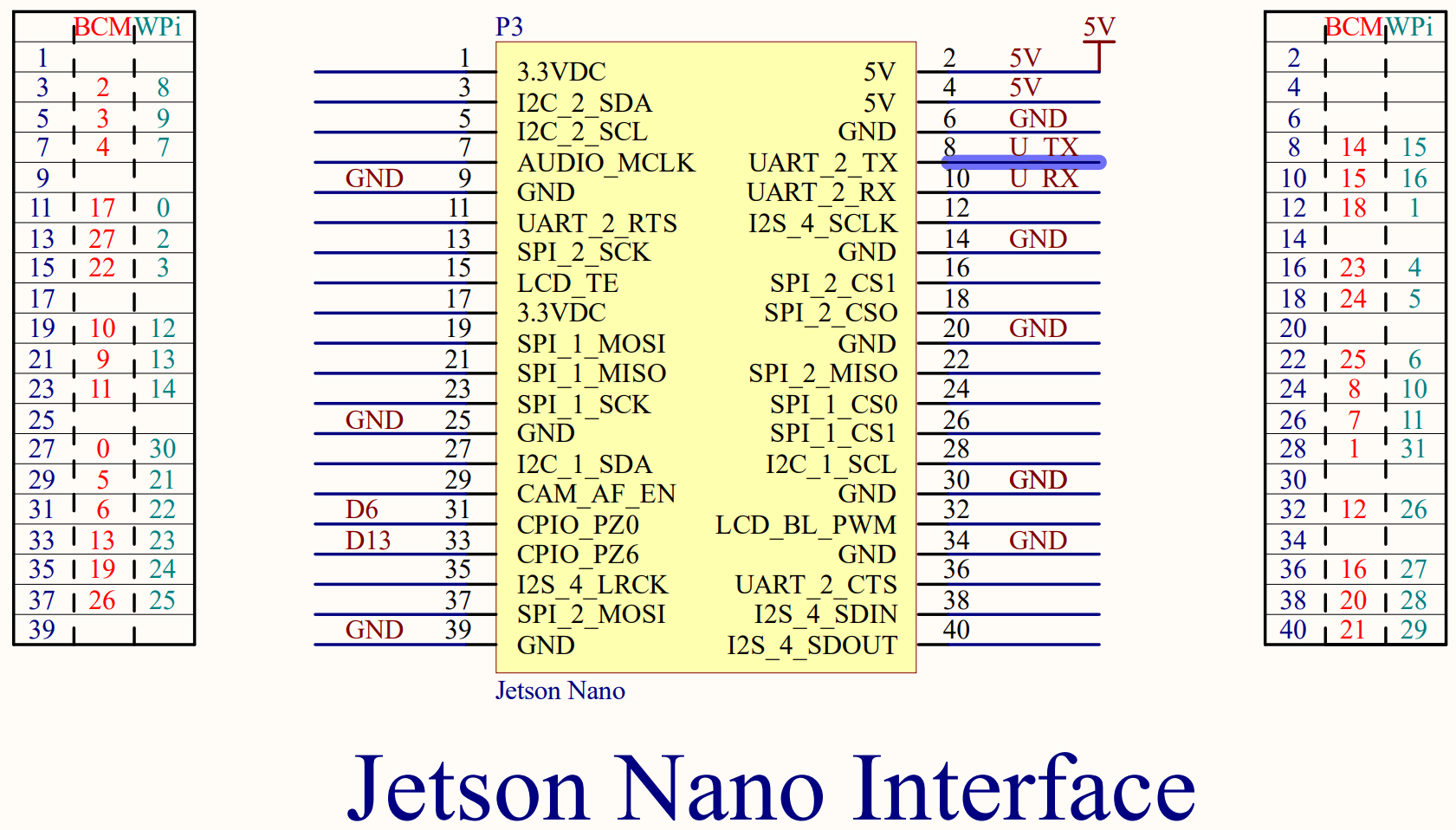
Waveshare Jetson Interface
Here you can see that the Waveshare board connects to some voltage and ground lines on the 40-pin interface. The only pins related to functionality used are pins 8 and 10 on the Jetson, which connect the Jetson’s UART to the SIMCOM 7600’s UART, and pins 31 and 33 on the Jetson, which connect to pins labeled D6 and D13 on the Waveshare board. Let’s trace these lines.
The two UART lines don’t connect directly to the SIMCOM 7600X. Instead they pass through a pair of switches and an integrated circuit identified as TXB0108EPWR. According to a datasheet (PDF), this circuit is a level shifter.
This circuit isn’t providing any additional signals. It allows the SIMCOM 7600, which uses 1.8 volt signaling, to communicate with the Jetson Nano over 3.3 volt signaling. The two switches allow the SIMCOM 7600’s UART and Jetson’s UART to be disconnected from each other. It is also possible to connect directly to the 3.3volt side of this circuit through pins exposed on the board.
Waveshare UART switch
There’s a schematic for the USB port. There’s nothing significant in the USB connection that you need to know. When I first got my hands on this board I was wondering why there were interfaces for both USB and a UART. Why are there two connections? This was answered by reading the SIMCOM 7600 documentation. The 7600 can accept AT commands over either interface and perform data transfers over either interface. The USB port is set to suspend if it is not used within some time period. It becomes active again during certain wake events.
In the Waveshare Wiki, developers are instructed to set a pin of the Jetson Nano to high and then low to ensure that the Wavesare device is turned on. The following is a script that can Waveshare provides for doing this.
There is not an explanation given as to what this is doing. GPIO200 is connected to pin 31 on the Jetson’s 40 pin header. Pin 31 leads to a pin labeled D6 on the board. What does pin D6 do? On the schematic we find that D6 terminates on a jumper.
D6 on Schematic
Layouts on an electrical schematic don’t necessarily map spatially. Looking at the physical connector in question, we can see more of what it does.
Closeup of D6
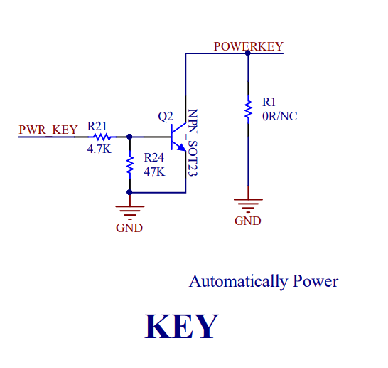
There is a jumper that can either bridge D6 to PWR, or bridge the 5V supply to power. In the above since PWR and 5V are connected, the PWR line will always be highm and pin 31 on the Jetson Nano is free for other purposes. If D6 and PWR are bridged, then the Jetson controls the power state of the board. The SIMCOM 7600 could go to a lower power mode for a number of reasons. This could include receiving a command instructing the SIMCOM 7600 to go to a lower power state. Pulsing this line will wake the SIMCOM 7600 up. If we look a little deeper at the schematic, we find PWR does not go directly to the SIMCOM 7600. It passes through another circuit.
Circuit for PWR signal
The end of the circuit labeled POWERKEY is connected to the SIMCOM 7600’s line of the same label. According to the SIMCOM 7600 documentation, connecting the power line to ground will power the unit on. (the POWERKEY line is connected to positive 1.8V internally within the SIMCOM 7600). The end result of this circuit could almost be viewed as being like an inverter; the high voltage from D6 or PWR results in the POWERKEY pin connecting to ground (low signal) and powering on. Sending a low signal to PWR causes the POWERKEY to be driven high by it’s internal resistor, which powers the SIMCOM 7600X off.
There is a circuit labeled “Flight Mode” that does something similar. The Flight Mode circuit bridges Pin 33 from the Jetson Nano to a pin on the SIMCOM 7600X labeled “Flight Mode.” As you may have inferred from using a phone, activating Flight Mode disables the radios within the SIMCOM 7600X.
Flight Mode circuit
There are a few other components on the schematic that don’t involve any signaling with the Jetson Nano. Of course, there is also the circuit that connects to the SIM card. Waveshare has also supplied a circuit for interfacing with earphones and a microphone. To use this feature you only need to connect a headset to the jack on the board.
There are three more interfaces on the schematic for the antennas. Two of these antennas are self-explanatory. The GNSS connector for a GPS antenna. The Main connector for a cellular antenna. There is a third antenna that is labeled as AUX on the Waveshare board, and DIV Ant on the schematic. While not strictly necessary, connecting an antenna to this connector can enhance the 4G performance of the SIM 7600.
That covers all of the circuits that connect to the Waveshare 7600X 4G.
Posts may contain products with affiliate links. When you make purchases using these links, we receive a small commission at no extra cost to you. Thank you for your support.
I installed the CUDA SDK on Linux. The SDK also updates the NVIDIA video driver. After the installation had run a message printed saying that the installation had completed with errors. I checked the log file and saw the installation had failed on a driver installation. After rebooting the screen was black. The computer was still working and responding to network requests. It just couldn’t display anything. I was able to get the screen to work in safe mode but the video card otherwise was outputting all black pixels.
Thankfully since the computer still responded to network request I was able to SSH into it and use apt-get to get a new driver installed.
In previous posts on the NVIDIA Jetson posts I’ve talked about getting the device setup and some additional accessories that you may want to have. The OS image for the NVIDIA Jetson already contains a compiler and other development software. Technically someone can start developing with the OS image as it is when it ships. But it is not desirable to develop this way.
There may be some things that you prefer to do on your primary computer and you’d like to be able to control the Jetson from your primary machine. The OS image for the Jetson already has SSH enabled. If you are using a Windows machine and net an SSH client I suggest using PuTTY for Windows. It’s a great SSH client and also works as a telnet or serial console when needed. It’s available from https://www.putty.org/.
When Putty is opened by default it is ready to connect to a device over SSH. You only need to enter the IP address to start the connection. Once connected enter your account name and password and you’ll have an active terminal available. For copying files over SSHFTP I use WinSCP (available from https://winscp.net/).
For development on the device I’ve chose Visual Studio Code as my IDE. Yes, it runs on ARMs too. There are a number of guides available on how to get Visual Studio Code recompiled and installed for an ARMS system. The one that I used is available from code.headmelted.com. In a nutshell I followed two steps; I entered a super user session with the command
su -s
Then I ran the following (which downloads a script from the head melted site and runs it).
The script only takes a few moments to run. After it’s done you are ready to start development either directly on the board or from another machine.
To make sure that everything works let’s make our first program with the Jetson Nano. This is a “Hello World” program; it is not going to do anything substantial. Let’s also use make to compile the program. make will take care of seeing what needs to be built and issuing the necessary commands. Here it’s use is going to be trivial. But I think starting with simple use of it will give an opportunity for those that are new to it to get oriented with it. Type the following code and save it as helloworld.cu
#include

__global__ void cuda_hello()
{
    printf("Hello World from GPU!\n");
}

using namespace std;

int main()
{
	cout << "Hello world!" << endl;
	cuda_hello<<>>();
	return 0;
}
We also need to make a new file named makefile. The following couple of lines will say that if there is no file named helloworld (or if the file is out of date based on the date stamp on helloworld.cu) the to compile it using the command /usr/local/cuda/bin/nvcc helloworld.cu -o helloworld
Note that there should be a tab on the second line, not a space.
Save this in the same folder as helloworld.cs.
Type make and press enter to build the program. If you type it again nothing will happen. That’s because make sees that the source file hasn’t changed since the executable was build.
Now type ./helloworld and see the program run.
Congratulations, you have a working build environment. Now that we can compile code it’s time to move to something less trivial. In an upcoming post I’ll talk about what CUDA is and how you can use it for calculations with high parallelism.
I pre-ordered the NVIDIA Jetson Nano and had the opportunity to have my first experiences with it this week. For those that are considering the Nano I give you the gift of my hindsight so that you can have a smoother experience when you get started. My experience wasn’t bad by any measure. But there were some accessories that I would have ordered at the same time as the Jetson so that I would have everything that I needed at the start. I’ve also made a YouTube video covering this same information. You can view it here.
How does the Nano Compare to Other Jetson Devices?
The Jetson line of devices from NVIDIA can be compared across several dimensions. But where the Jetson Nano stands out is the price. It is priced at about 100 USD making it affordable to hobbiest. Compare this to the Jetson TK1 which is available for about 500 USD or the Jetson Xaviar available for about 1,200 USD. Another dimension of interest is the number of CUDA cores that the units have. CUDA cores are hardware units used for parallel execution.
In addition to the cores the other Jetson kits have support for other interfaces, such as SATA for adding hard drives or a CAN bus for interfacing with automotive systems. For someone getting started with experimentation the Jetson Nano is a good start.
What is In the Box?
Not much. You’ll find the unit, a small paper with the URL of the getting started page, and a cardboard cutout used for supporting the card on the case.
Most of the things on that list you might already have. For an SD card get one at least 8 gigs or larger.
Power Supply
A power supply! It uses a 5 volt power supply like what is used in a phone. Well, kind of. Don’t expect for any of your 5V power supplies to work. I found the hard way that many power supplies don’t deliver the amount of current that is needed. Even if the power supply is capable a USB cable might not allow the needed amount of current to pass. If this happens the device will just cut off. There’s no warning, no error message, nothing. It just cuts off. I only came to realize what was going on after I used a USB power meter on the device. I used a power meter for USB-A, but the board already has contacts for using a USB-C port. Depending on when you get your board it may have a USB-C port on it (possibly, speculatively).
A Raspberry Pi camera will work. But I used a Microsoft LifeCam. There are a number of off-the-shelf webcams that work. You’ll only need a camera if you plan on performing visual processing. If your going to be processing something non-visual or if your visual data is coming from a stream (file, network location) then of course this won’t be necessary.
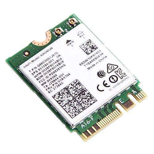
WiFi
You have two options for WiFi. One option is a USB WiFi dongle. There are a number of them that are compatible with Linux that will also work here. I am using the Edimax EW-7811UN. After being connected to one of the USB ports it just works. Another solution is to install a WiFi card into the M.2 adapter. It might not be apparent at first, but there is a M.2 slot on the case. I chose to use this solution. Like the USB solution there’s not much to be done here; inserting the WiFi adapter into the slot, securing it is most of the work. Note that you’ll also need to connect antennas to the wireless card.
Operating System Image
The instructions for writing a new operating system image are almost identical to that of a Raspberry Pi. The difference is the URL from which the OS image is downloaded. Otherwise you download an image, write it to an SD card, and insert it into the Nano. Everything else will be done on first boot. You’ll want to have a keyboard connected to the device so that you can respond to prompts. When everything is done you’ll have an ARMs build of Ubuntu installed.
For writing the OS image I used balenaEtcher. It is available for OS X and Linux. The usage is simple; select an OS image, select a target drive/memory device, and then let it start writing to the card. The process takes a few minutes. But once it is done put the SD card in the Jetson Nano’s memory card slot.
Case Options
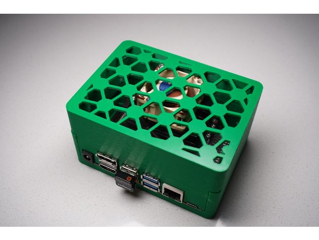
A case may be one of the last things that you need. But if you seriously have interest in having the Jetson Nano I suggest ordering the case at the start. There are no off-the-shelf cases available for purchase for the Nano. But there are a few 3D printable plans for the Jetson Nano. I’ve come across three and have settled on one.
The case is a bit thick, but it isn’t lacking for ventilation. The case height accommodates a fan. While the design doesn’t include any holes for mounting antennas for WiFi drilling them is easy enough.
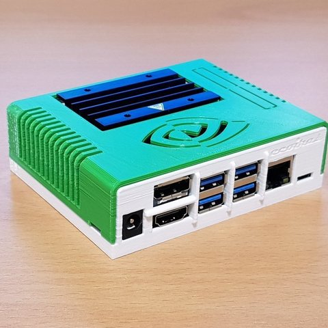
The NanoBox will envelope the Jetson leaving the heat sink almost flush with the case. I’d suggest this one if you plan don’t plan to use a fan on the Jetson. If you ever change your mind and decide that you want to have a fan it can be added. But it will be on the outside of the case.
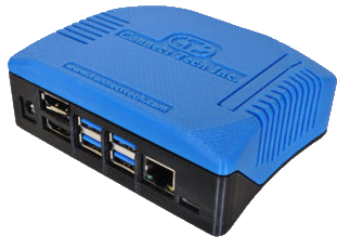
There’s not much to say about this case. It fully envelopes the Jetson Nano. But I’ve got questions about the cooling effectiveness of this case.
It’s Assembled and Boots Up. Now What?
Once the Jetson is up and running the next thing to do is to setup a development environment. There is a lot of overlap between targeting the Jetson series and targeting a PC that has an NVIDIA GPU. What I write on this will be applicable to either except for when I state otherwise.
If you’ve installed Visual Studio 2019 and are trying to work with CUDA there are a couple of problems that you’ll encounter. The first is going to be an error that you receiving when trying to opan any CUDA project about missing properties. This is from the CUDA installer placing some of the files in the wrong place. It places the files based on what was in Visual Studio 2019 Preview. It was only recently that the full release of 2019 was made available (and for the full release theses files need to go into a different place). To work around that see this post for where to move the missing files to.
Once that is resolved the next problem is that the CUDA project templates are missing. An NVidia representative in the NVidia developer forums acknowledged the problem and says a fix will come in an upcoming release. Until then the current solution is to grab an existing CUDA project and rename it. If you need an existing CUDA project you can find them in the folder for the NVidia CUDA samples or download one from here:
If you try to install the nVidia CUDA SDK and plan to use Visual Studio 2019 there’s an additional manual step that you’ll need to take. The installer available for the current version of CUDA (10.1) doesn’t specifically target the recently released Visual Studio 2019, but it will mostly work with it. I say “mostly” because after installing it you’ll find that the CUDA related project templates are missing and you can’t open the sample projects.
Fixing this is as simple as copying a few files. Copying everything from the following folder