I’m working on a project with a Raspberry Pi Pico to control some devices over IR (infrared). Many IR controlled devices pulse the IR LED at a frequency of about 38 kilohertz so that it can be differentiated from other stray IR light sources. What is a good way to turn a pin on and off 38,000 times per second? As a starting point, I used one of the PICO examples that generates a square wave.
The most obvious way would be to write code in a cycle that activates a pin, waits for a moment, and then deactivates a pin. That code would look similar the following.
gpio_put(LED_PIN, true);
sleep_us(12);
gpio_put(LED_PIN, false);
sleep_us(12);
There are 1,000,000 us (microseconds) in a second. The total of the two waits together is 24 us. 1,000,000/24 is 38,461. There will be additional time consumed on the calls to set the pins, making the actual number of times that this code can run in a loop per second to be slightly lower than 38,461. But it is close enough to be effective.
There is a lot of room for improvement in approach. A significant problem with this code is that it consumes one of the execution cores of the processor to be in wait states. This is a waste of a processor core; there’s other work that it could be doing in that time. Let’s take a step towards a better approach. While there are several elements that would be part of a better solution, I want to focus on one.
In addition to the primary cores, the Pi Pico also has processors that are made specifically for operations on a few of the GPIOs. These make up the Programmable IO (PIO) system. This processor is simple. There are two blocks of 4 processors (8 total). There are only 9 instructions that the processor can execute. But its execution of these instructions is deterministic, taking 1 clock cycle per instruction. We can also set an instruction to wait up to 31 additional cycles before going to the next instruction.
These execution units give a developer the following hardware to work with.
- Two general purpose registers, labeled X and Y
- An Input and Output shift register
- A Clock Divider for modifying the execution speed of the PIO unit
- Access to the Pico’s IRQ registers
- Mapped and direct access to the GPIO pins
Because the execution units support mapped IO, the same program could run on multiple PIO units and be assigned to different GPIOs
PIO is programmed with PIO Assembler (pioasm). Each PIO unit has two general purpose records, labeled X and Y. There are only 9 instructions, each of which is encoded as a 16-bit structure of the instructions and the operands. We don’t need all the instructions for the task I’m trying to accomplish here. I’ll list all nine of them.
- IN – shift up to 32 bits from a GPIO or register to the input shift register
- OUT – shift up to 32 bits from the Output Shift Register to a pin or register
- PULL – move the contents of the Tx FIFO to the output shift register
- PUSH – move the contents of the input shift register to the Rx FIF and clear the ISR.
- MOV – Copy data from a register or pin to some other register or pin.
- IRQ – Sets or clears an IRQ flag
- SET – Write an immediate value to a pin or register
- JMP – Jumps to an absolute address within the PIO instruction memory
- WAIT – stall execution until a specific pin or IRQ flag is set or unset
Since all I am trying to do is set a pin to alternating states, the only instruction I need for this program is the SET instruction. One call to SET will activate a pin. Another call will deactivate it. The part where more attention must be given to detail is to ensure that this happens about 38,000 times per second. There will be more code in this posting about setting PIO attributes than in the PIO code itself. Let’s address the easier part, the PIO program.
The PIO program itself is only 7 lines. Most of these lines are not executable code. The first line lets the software tools know what version of the pio spec is being used. The second line sets the name of the program. This name will propagate to other auto-generated elements in code. It isn’t only notational. In the third line, I specify that the pins that are assigned to the program should be set to output pins. There will only be one pin assigned to the program.
The first line of executable code is the call to “set pins , 1 [1]”. This sets the assigned pin to high. The [1] next to the instruction causes the execution unit to stall for a clock cycle. This line of code takes 2 clock cycles to execute. The next line sets the pin to the low state.
.pio_version 0
.program squarewave
    set pindirs, 1  ; Set pin to output
loop:
    set pins, 1  [1]
    set pins, 0
    .wrap
The last line of the program, .wrap, marks the end of the executable code. While .wrap isn’t itself an instruction, implicitly there is a JMP instruction hat gets executed when this line is reached. The program will either jump to the beginning of the code (if no jump target is specified) or it will jump to a line with .wrap_target (if such a line is entered). The code that gets executed could be written as follows.
loop:
set pins, 1 [1] ; Set pin (1-cycle) + delay (1-cycle) = 2-cycles
set pine, 0 ; 1-cycle
 jmp loop ; 1-cycle
You might have the question of why I have a delay. I want the output to have a 50% duty cycle. If I wrote that code without any delays, then the pin would be high for 1/3 or the cycle and low for 2/3, since the pin would remain low while the jump instruction was executing.
When the code is compiled, a C++ header file is emitted. The C++ header contains the program as an array of numerical data. It also defines some additional functions that provide support and initialization for the program. If we want additionally C/C++ code that is associated with our PIO program, we can embed C/C++ code in our PIO file. This ensures that if the PIO is distributed, the C/C++ code will always be distributed with it. We just need to ensure that it is embedded between “% c-sdk {“ and “%}”.
For my program, I have added a function named “squarewave_program_init” that performs a few tasks. It performs the some initialization steps for my PIO program, including applying a clock divider to lower the frequency at which the program runs.
.pio_version 0
.program squarewave
    set pindirs, 1  ; Set pin to output
loop:
    set pins, 1  [1]
    set pins, 0
    .wrap

% c-sdk {
    static inline void squarewave_program_init(PIO pio, uint sm, uint offset, uint pin, float div)
    {
        pio_sm_config c = squarewave_program_get_default_config(offset);
        sm_config_set_out_pins(&c, pin, 1);
        pio_gpio_init(pio, pin);
        pio_sm_set_consecutive_pindirs(pio, sm, pin, 1, true);

        sm_config_set_clkdiv(&c, div);
        sm_config_set_set_pins(&c, pin, 1);
        pio_sm_init(pio, sm, offset, &c);
        pio_sm_set_enabled(pio, sm, true);
    }
%}
We still need to calculate a divider frequency. The Raspberry Pi Pico can run up to 133 MHz. They will generally be clocked between 125 MHz and 133 MHz. To get the frequency at which the Pico is running, we can use the function clock_get_hz(). Each loop of my PIO program needs 4 instructions. To run at 38KHz, I need for the PIO program to run with a clock rate of 38,000 x 4 times per second. The PIO clock rate needs to be at 152 KHz. The divider amount needs to be the result of the clock frequency divided by 152,000.
static const float pio_freq = 38000*4;
float div = (float)clock_get_hz(clk_sys) / pio_freq;
The last couple of things that must be done is that I need to grab an available PIO unit and assign my program to it. Then I need to enable my program to run.
bool success = pio_claim_free_sm_and_add_program_for_gpio_range(&squarewave_program, &pio, &sm, &offset, CARRIER_PIN, 1, true);
 hard_assert(success);
squarewave_program_init(pio, sm, offset, CARRIER_PIN, div);
After that last line of code runs, the PIO will be active and running the program. It will stay active until I deactivate it (or the Pico loses power). If I needed to stop the PIO program and deallocate the use of resources, I can perform that with a call to pio_remove_program_and_unclaim_sm();
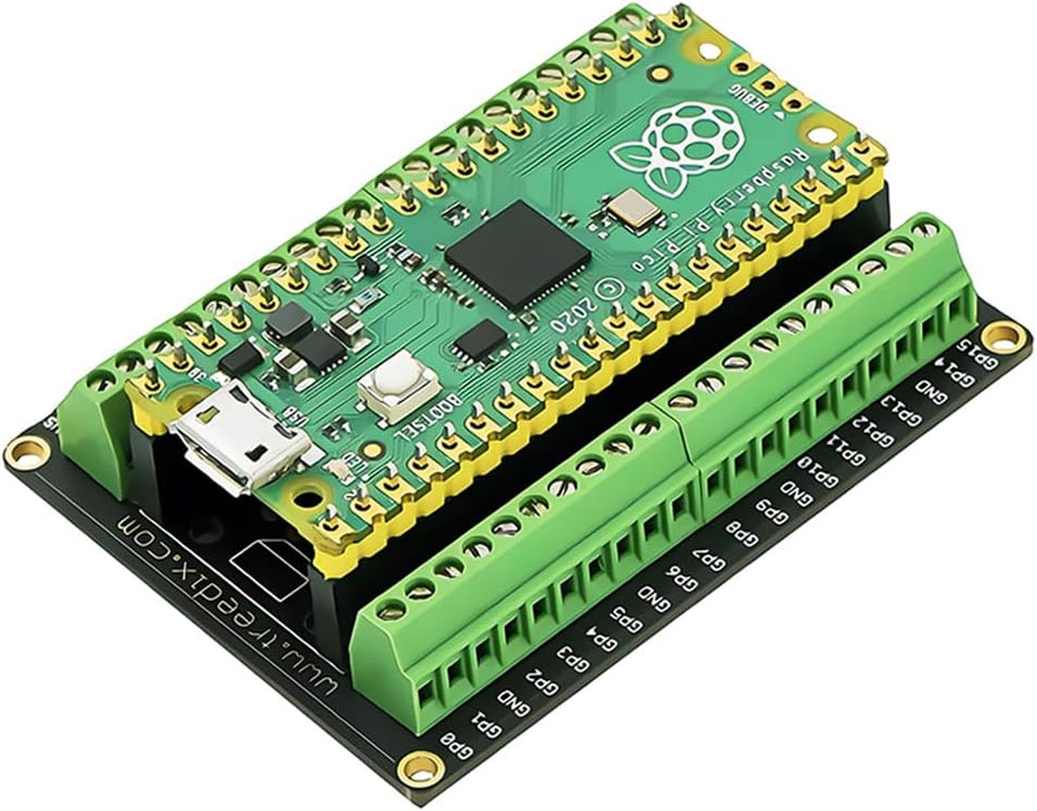
The Pico that I am using is connected to a break-out board that shows the status of each one of the GPIOs. (See A Pi Pico Breakout Board – j2i.net).While 38KHz is too fast to observe with the naked eye, when I run the program, the first indication that it is operating as expected is that the light on the target pin appears to be illuminated with a slightly lower intensity than the other pins. This is expected, since the status light is unpowered 50% of the time.
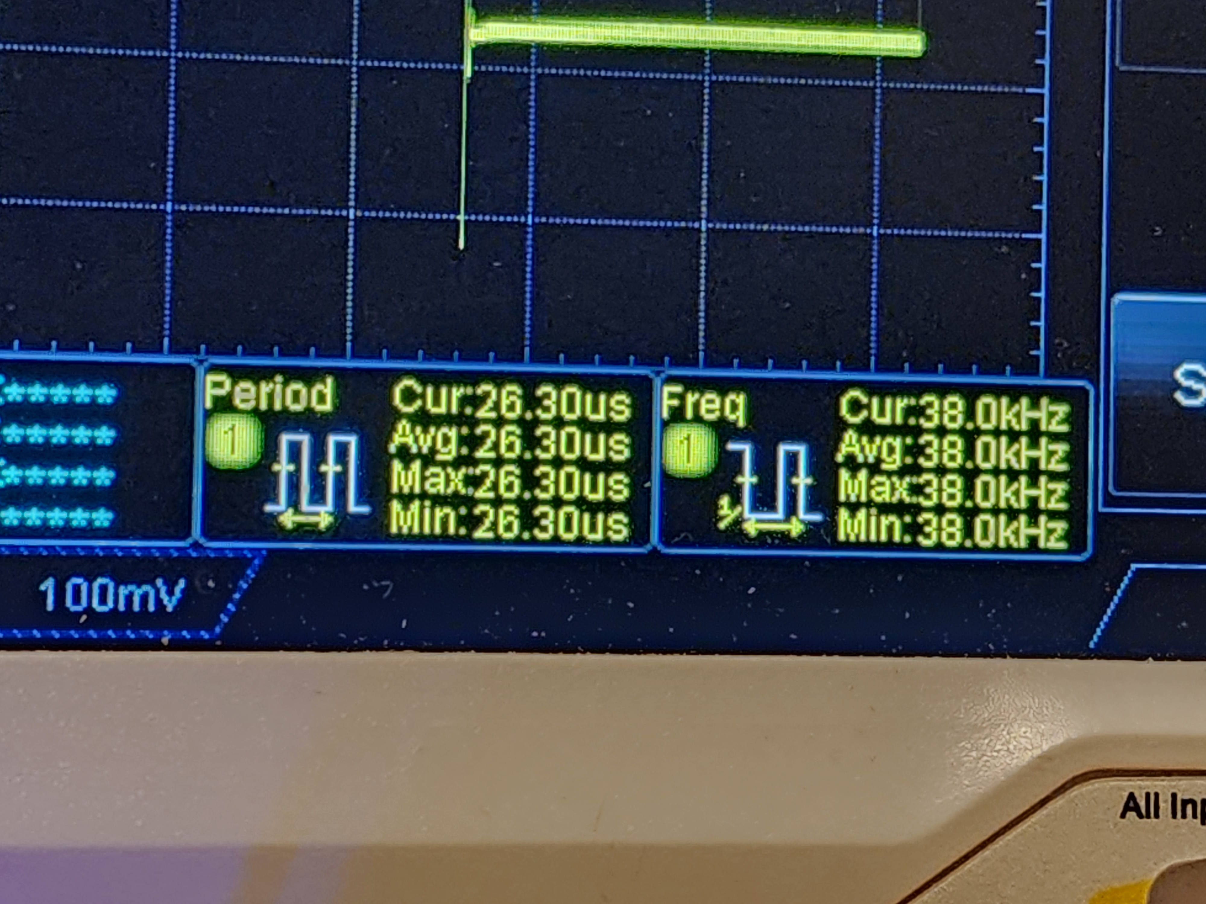
To know it is working, we can use an oscilloscope. Connecting the scope to the pin, I see a square wave.

Checking the frequency on the scope, I see a reading of 38.0 KHz.
This gives me a carrier for IR signalling. With that accomplished, I now need to turn this output on and off in a sequence to communicate an IR message. If you’d like to see the code used for making this post in the form it was in at the time this post was published, you can find it on GitHub at this URL.
https://github.com/j2inet/irdetect/tree/addingGpio
Posts may contain products with affiliate links. When you make purchases using these links, we receive a small commission at no extra cost to you. Thank you for your support.
Mastodon: @j2inet@masto.ai
Instagram: @j2inet
Facebook: @j2inet
YouTube: @j2inet
Telegram: j2inet
Bluesky: @j2i.net