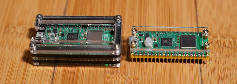
I picked up a few Pi Pico cases. Both provide different protection for the units. I also find them to be aesthetically pleasing additions to have on the board. They both protect the top and underside of the board. The most significant difference is whether they also protect the pins that may be soldered to the board.
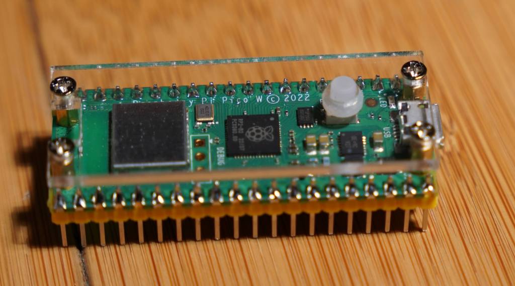
One of the cases is minimalistic. It sandwiches two pieces of acrylic around the board. There are spaces so that the acrylic on the top side isn’t resting on the board and has enough space to hold an extension so that the BOOTSEL button is still accessible. But this case was clearly made for the Picos that don’t have the WiFi chip. The debug header pins are in different places on the Picos with Wi-Fi and without. If you don’t use the debug header pins, this won’t be an issue. The lower acrylic is just wide enough to cover the bottom of the board between the header pins. This case protects the board itself, but not the pins that are connected to it. I use this on a Pico that is connected to a breakout board. That it doesn’t cover the pins gives me enough clearance to easily plug it in.
C4Labs Case
C4Labs Case
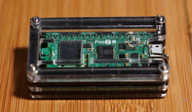
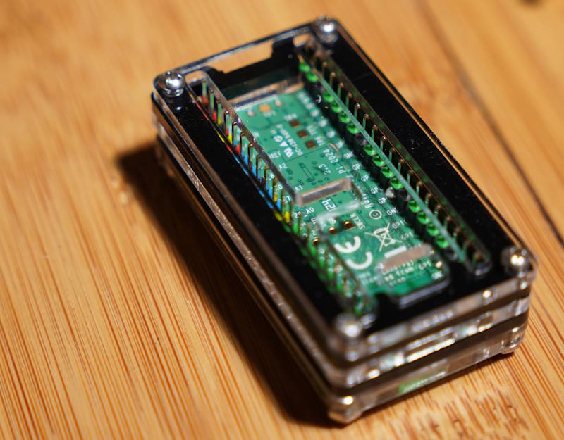
The other case, from C4Labs, is also made of acrylic pieces. Though it is many more pieces sandwiched together to completely envelope the Pico circuit board, the pins, and the debug header. This case was made to universally fit the Picos with and without Wi-Fi. There are cutouts for either position of the debug header. Since the pins are completely enveloped, there are restrictions on how one might connect something to it. Jumper wires will connect to the pins without trouble.
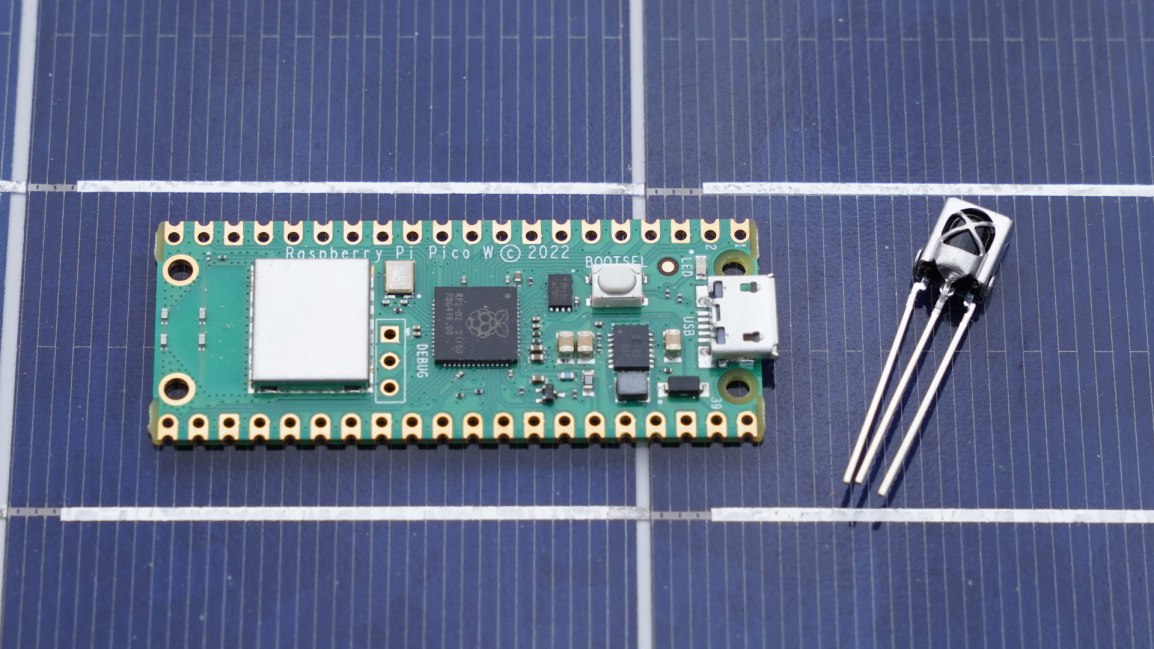
I cannot use this case with the breakout board that I have though. Parts of the case conflict with other connectors that I have on my breakout board. However, the area in the case in which the pins would extend could potentially be used to hold a small amount of other electronics. I’m working on an IR control project, and I might place an IR Emitter and detector within this space.
These cases are available on Amazon. The minimalistic case is available by itself or with a Pi Pico. You can purchase them through the following links. Note that these are affiliate links. I make a small commission if you purchase through these links.
Posts may contain products with affiliate links. When you make purchases using these links, we receive a small commission at no extra cost to you. Thank you for your support.
In a previous post, I mentioned that I was re-introducing myself to development for the Pi Pico. The Pico is a microcontroller, often compared to an Arduino, that can be programmed from a Linux, Mac, or Windows machine. The Pico is based on the RP2040 chip. This is an ARM based Cortex-M0 dual core processor, generally running between 125 and 133 MHz. It has 264 KB of SRAM, 2 MB of flash memory, 26 general purpose IO pins, some of which support additional functionality. The other functionality overlaid on these pins includes
2 UART pins
2 SPI controllers
2 I2C controllers
16 PWM channels
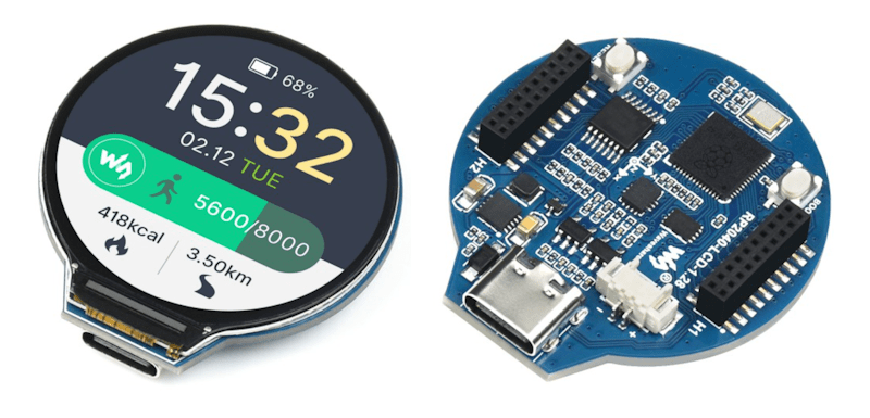
There are several development boards that use the RP2040. Collectively, I generically refer to all of these as Pico. It is a bit easier to say then “RP2040 based board.”
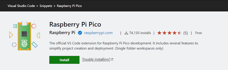
I already had a few machines setup for development for the Raspberry Pi Pico. While that procedure still works, as do those development machines, I was recently reintroducing myself to Pico development. I started with a clean installation and went to the currently published instructions for setup. The more recent instructions are a lot easier to follow; there are less dependencies on manually setting paths and downloading files. The easier process is made possible through a Visual Studio Code plugin. This extension, which is still labeled as a zero version at the time that I am making this post (0.17.3) adds project generation and sample code along with scripts and automations for common tasks. To get started, just Install the Raspberry Pi Pico Visual Studio Code Extension. Once it is installed, you’ll have a new icon on the left pane of VS Code for Pico related tasks.
The first time you do anything with this icon, expect it to be slow. It installs the other build tools that it needs on-demand. I prefer to use the C++ build tools. Most of what I write here will be focused on that. I’ll start with creating a new C++ project. Double-clicking on “New C/C++ Project” from the Pico tools panel gets the process started.
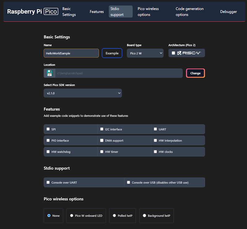
This will only be a “Hello World” program. We will have the Pico print a message to a serial port in a loop. The new project window lets us specify our target hardware, including which hardware features that we plan to use. Selecting a feature will result in the build file for the project linking to necessary libraries for that feature and adding a small code sample that access that feature. Select a folder in which the project folder will be created, enter a project name, and check the box labeled “Console over USB.” After selecting these options, click on the “Create” button.
This is the part that takes a while the first time. A notification will show in VS Code stating that it is installing the SDK and generating the project. The wait is only a few minutes. While this is executing, it is a good time to grab a cup of coffee.
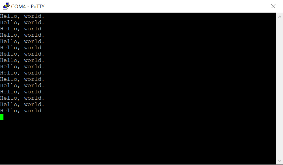
When you get back, you’ll see VS Code welcome you with a new project. The default new project prints “Hello, world!\n” in a loop with a 1 second delay. Grab your USB cable and a Pico. We can immediately start running this program to see if the build chain works. On the Pico, there’s a button. Connect your USB cable to your computer, then connect the Pico, making sure you are holding down this button as you connect it. The Pico will show up on your computer as a writable drive. After you’ve done this, take note of which serial ports show up on your computer. In my case, I’m using Windows, which shows that Com1 is the only serial port. In VS Code, you now have several tasks for your project that you can execute. Double-click on Run Project (USB). The code will compile, deploy to the Pico, and the Pico will reboot and start running the code.
Check to see what serial ports exist on your computer now. For me, there is a new port named Com4. Using PuTTY, I open Com4 at a baud rate of 115,200. The printed text starts to show there.
Using the USB UART for output is generally convenient, but at time you may want to use the USB for other features. The USB output is enabled or disabled in part through a couple of lines in the CMakeList.txt file.
The 1 and 0 can be interpreted as meaning enable and disable. Swap these values and run the project again by disconnecting the Pico, reattach while pressing the button, and then selecting the Run Project (USB) option from VS Code. When you run the code this time, the output is being transmitted over GPIO pins 0 and 1. But how do we read this?
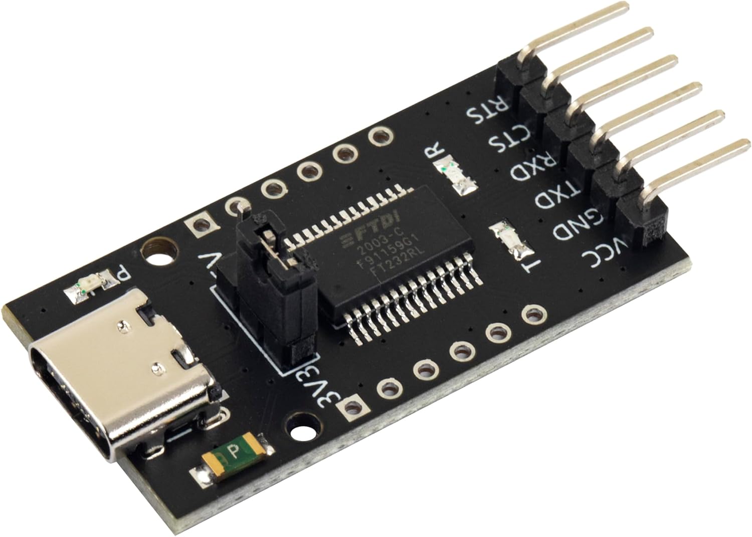
FTDI USB
FTDI is the name of an integrated circuit manufacturer. For microcontroller interfacing, you might often see people refer to “FTDI USB” cables. These are USB devices that have 3 or 4 pins for connecting to other serial devices. These are generally cheaply available. The pins that we care about will be labeled GND (Ground), TX (Transmit), and RX (Receive). The transmit pin on one end of a serial exchange connects to the receive end on the other, and vice versa. On the Pico, the default pins used for uart0 (the name of our serial port) are GP0 for TX and GP1 for RX. When connecting an FTDI device, connect the FTDI’s RX to the Pico’s TX on GPO, then the FTDI’s TX to the Pico’s RX (on GP1), and finally the FTDI’s ground to the Pico’s ground.
GPIO – Setting a Pin
Many, Pico’s have a LED attached to one of the pins that is immediately available for test programs. While many do, not all do. On the Pi Pico and Pi Pico 2, GPIO 25 is connected to a LED. On the Pi Pico W, the LED is connected to the WiFi radio and not the RP2040 directly. For uniformity, I’ll drive an external LED. I’ve taken a LED and have it connected in series with a resistor. 220Ω should be a sufficient value for the resistor. I’m connecting the longer wire of the LED to GP5 and the shorter pin to ground.
In the code, the pin number is assigned to a #define. This is common, as it makes the code more flexible for others that may be using a different pin assignment. Before we can start writing to the pin, we need to gall an initialize function for the pin number named gpio_init(). After the initialization, we need to set the pin to be either in input or output mode. Since we are going to be controlling a LED, this needs to be output mode. This is done with a call to gpio_set_dir() (meaning “set direction”) passing the pin number as the first argument, and the direct (GPIO_IN or GPIO_OUT) as the second argument. For writing, we use GPIO_OUT. With the pin set to output, we can drive the pin to a high or low state by calling gpio_put(). The pin number is passed in the first argument, and a value indicating whether it should be in a high or low state in the second argument. A zero value is considered low, while a non-zero value is considered high. To make it apparent that the LED is being driven by our control of the pin (and not that we just happened to wire the LED to a pin that is always high) we will turn the light on and off once per second. In a loop, we will turn the light on, wait half a second, turn the light off, and wait again.
When we run the code now, we should see the light blink.
Up Next: Programmable IO – The Processor within the Processor
While the GPIO system can be manipulated by the main processor core, there are also smaller processors on the silicon that exist just for controlling the GPIO. These processors have a much smaller reduced set but are great for writing deterministic code that controls the pins. This system of sub-processors and the pins that they control are known as “Programmable IO.” They are programmed using assembler. There’s much to say about PIO. In the next post that I make on the Pico, I’ll walk you through an introduction to the PIO system.
Posts may contain products with affiliate links. When you make purchases using these links, we receive a small commission at no extra cost to you. Thank you for your support.
I’ve used a Pi Pico before. But it has been a while, and I decided to jump back into it in furtherance of some other project I want to do. I’m specifically using a Pico W on a Freenove breakout board. The nice thing about this board is that all the GPIOs have status LEDs that lets you monitor the state of each GPIO visually. For those that might have immediate concern, the LEDs are connected to the GPIO via hex inverters instead of directly. This minimizes the interaction that they may have with devices that you connect to them.
Blinking the Light
About the first program that one might try with any micro controller is to blink a light. I accomplished that part without issue. But for those that are newer to this, I’ll cover in detail. Though I won’t cover the steps of setting up the SDK.
I’ve made a folder for my project. Since I plan to evolve this project to work with an infrared detector, I called my project folder irdetect. I’ve made two files in this folder.
CMakeList.txt – the build configuration file for the project
main.cpp – the source code for the project
For the CMakeList.txt file, I’ve specified that I’m using the C++ 23 standard. This configuration also informs the make process that main.cpp is the source file, and that the target executable name will be irdetect.
cmake_minimum_required(VERSION 3.13)

include(pico_sdk_import.cmake)

project(test_project C CXX ASM)
set(CMAKE_C_STANDARD 11)
set(CMAKE_CXX_STANDARD 23) #Latest C__ Standard available
pico_sdk_init()

add_executable(irdetect
   main.cpp
)

pico_enable_stdio_usb(irdetect 1)
pico_enable_stdio_uart(irdetect 1)
pico_add_extra_outputs(irdetect)
The initial source code for blinking a LED is alternating the state of a random GPIO pin. Since I’m using a breakout board with LEDs for all the pins, I am not restricted to one pin. For the pin I selected, it is necessary to call gpio_init() for the pin, and then set its direction to output through gpio_set_dir(). If you don’t do this, then attempts to write to the pen will fail (speaking from experience!).
#include <stdio.h>
#include "pico/stdlib.h"
#include "hardware/gpio.h"
#include "pico/binary_info.h"
#include "pico/cyw43_arch.h"


const uint LED_DELAY_MS = 250; //quarter second
#ifdef PICO_DEFAULT_LED_PIN
const uint LED_PIN = PICO_DEFAULT_LED_PIN;
#else
const uint LED_PIN = 15;
#endif


// Initialize the GPIO for the LED
void pico_led_init(void) {
	gpio_init(LED_PIN);
	gpio_set_dir(LED_PIN, GPIO_OUT);
}

// Turn the LED on or off
void pico_set_led(bool led_on) {
	gpio_put(LED_PIN, led_on);
}

int main()
{
	stdio_init_all();
	pico_led_init();

	while(true)
	{
		pico_set_led(true);
		sleep_ms(LED_DELAY_MS);
		pico_set_led(false);
		sleep_ms(LED_DELAY_MS);
	}
	return 0;
}
To compile this, I made a subfolder named build inside of my project folder. I’m using a Pico W. When I compile the code, I specify the Pico board that I’m using.
cd build
cmake .. -DPICO_BOARD=pico_w
make
Some output flies by on the screen, after which build files have been deposited into the folder. the one of interest is irdetect.u2f. I need to flash the Pico with this. The process is extremely easy. Hold down the reset button on the Pico while connecting it to the Pi. It will show up as a mass storage device. Copying the file to the device will cause it to flash and then reboot. The device is automatically mounted to the file system. In my case, this is to the path /media/j2inet/RPI-RP2
cp irdetect.u2f /media/j2inet/RPI-RP2
I tried this out, and the light blinks. I’m glad output works, but now to try input.
Reading From a Pin
I want the program to now start off blinking a light until it detects an input. When it does, I want it to switch to a different mode where the output reflects the input. In the updated source I initialize an addition pin and use gpio_set_dir to set the pin as an input pin. I set an additional pin to output as a convenience. I need a positive line to drive the input high. I could use the voltage pin with a resistor, but I found it more convenient to set another GPIO to high and use it as my positive source for now.
#include <stdio.h>
#include "pico/stdlib.h"
#include "hardware/gpio.h"
#include "pico/binary_info.h"
#include "pico/cyw43_arch.h"


const uint LED_DELAY_MS = 50;
#ifdef PICO_DEFAULT_LED_PIN
const uint LED_PIN = PICO_DEFAULT_LED_PIN;
#else
const uint LED_PIN = 15;
#endif
const uint IR_READ_PIN = 14;
const uint IR_DETECTOR_ENABLE_PIN = 13;


// Initialize the GPIO for the LED
void pico_led_init(void) {
        gpio_init(LED_PIN);
        gpio_set_dir(LED_PIN, GPIO_OUT);

        gpio_init(IR_READ_PIN);
        gpio_set_dir(IR_READ_PIN, GPIO_IN);

        gpio_init(IR_DETECTOR_ENABLE_PIN);
        gpio_set_dir(IR_DETECTOR_ENABLE_PIN, GPIO_OUT);
}

// Turn the LED on or off
void pico_set_led(bool led_on) {
        gpio_put(LED_PIN, led_on);
}

int main()
{
        stdio_init_all();
        pico_led_init();
        bool irDetected = false;
        gpio_put(IR_DETECTOR_ENABLE_PIN, true);
        while(!irDetected)
        {
                irDetected = gpio_get(IR_READ_PIN);
                pico_set_led(true);
                sleep_ms(LED_DELAY_MS);
                pico_set_led(false);
                sleep_ms(LED_DELAY_MS);
        }

        while(true)
        {
                bool p = gpio_get(IR_READ_PIN);
                gpio_put(LED_PIN, p);
                sleep_us(10);
        }
        return 0;
}
When I run this program and manually set the pin to high with a resistor tied to an input, it works fine. My results were not the same when I tried using an IR detector.
Adding an IR Detector
I have two IR detectors. One is an infrared photoresistor diode. This component has a high resistance until it is struck with infrared light. When it is, it becomes low resistance. Placing that component in the circuit, I see the output pin go from low to high when I illuminate the diode with an IR flashlight or aim a remote control at it. Cool.
I tried again with a VS138B. This is a three pin IC. Two of the pins supply it with power. The third pin is an output pin. This IC has a IR detector, but instead of detecting the presence of IR light, it detects the presence of a pulsating IR signal provided that the pulsing is within a certain frequency band. The IC is primarily for detecting signals sent on a 38KHz carrier. I connected this to my Pico and tried it out. The result was no response. I can’t find my logic probe, but I have an osciloscope. Attaching it to the output pin, I detected no signal. What gives?
This is where I searched on the Internet to find the likely problem and solutions. I found other people with similar circuits and problems, but no solutions. I then remembered reading something else about the internal pull-up resistors in Arduinos. I grabbed a resistor and connected my input pin to a pin with a high signal and tried again. It worked! The VS138B signals by pulling the output pin to a low voltage. I went to Bluesky and posted about my experience.
I updated my code, and it works! When I attach the detector to the scope, I also see the signal now.
Now that I can read, the next step is to start decoding a remote signal. Note that there are already libraries for doing this. I won’t be using one (yet) since my primary interest here is diving a bit further into the Pico. But I do encourage the use of a third-party library if you are aiming to just get something working with as little effort as possible.
Code Repository
While you could copy the code from above, if you want to grab the code for this, it is on GitHub at the URL https://github.com/j2inet/irdetect/. Note that with time, the code might transition to something that no longer resembles what was mentioned in this post.
Posts may contain products with affiliate links. When you make purchases using these links, we receive a small commission at no extra cost to you. Thank you for your support.
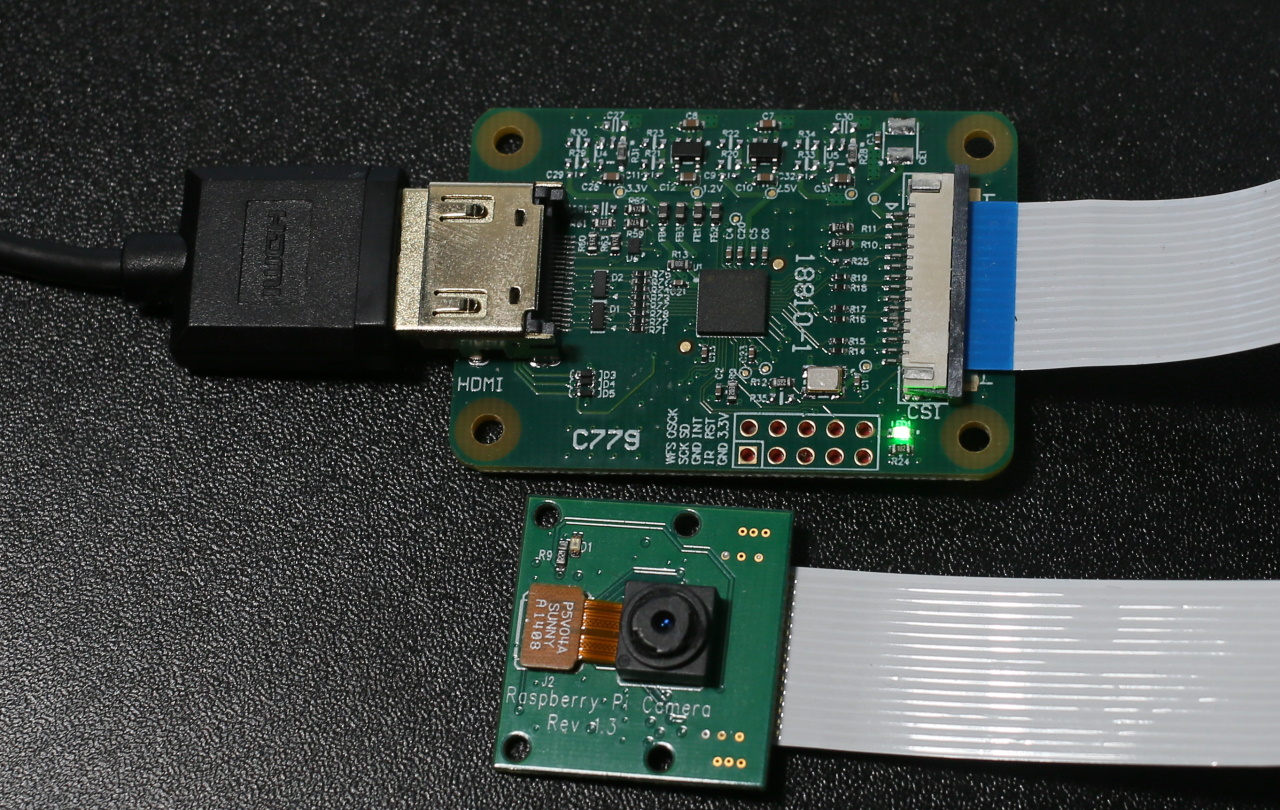
Back in January I tweeted about an HDMI capture device that for the Raspberry Pi. I’ve only recently have gotten a chance to use it. The device, known as the “HDMI to CSI-2 module”, works with the Raspberry Pi. Overall my experience was positive, though I found that this device has limitations that, if not previously known, can result in some frustration. The device connects to the CSI-2 camera interface and presents itself as a camera. The utilities and scripts that you may have used with the Raspberry Pi also work with this device without modifications. Along with the HDMI capture module the package contains the cable needed for connecting it to the full size Raspberry Pi and a second cable for use with a Raspberry Pi Zero.
One of the first uses that came to mind with this device is that I could use camera options beyond the official Pi cameras. The camera that I have about the house produce clean HDMI signals. They already have a range of lenses, ranging from some macro lenses for pictures of small items close-up and a 2132 millimeter Schmidt–Cassegrain for astrophotography.
My smallest lens next to my largest lens. Both of which are not available for use on the Pi through my digital camera.
The first time I tried to use the capture device with one of my cameras, it didn’t work. I received a non-descriptive error that is primarily associated with non-working or improperly installed cameras.
mmal: mmal_vc_component_enabled: failed to enable component: ENOSPC
mmal: camera component couldn't be enabled
mmal: main: Failed to create camera component
mmal: Failed to run camera app. Please check for firmware updates
Thankfully, this isn’t indicative of an actual hardware failure. The capture device works with a limited set of resolutions and refresh rates. For 1080p video signals, the maximum refresh rate is 25 fps.
Resolution
Refresh Rate (fps)
720p
50
720
60
1080i
50
1080p
24
1080p
25
Supported Resolutions
After making adjustments to the output settings of my camera, I was successful in using it with the HDMI capture.
The camera was the first device that came to mind, but it could work with non-camera HDMI sources too. I connected a Nintendo Switch to the device and it captured from the switch just fine. Provided that the signal is within the resolution and FPS range and is not an encrypted (HDCP) signal, it works.
Comparing the HDMI capture device to the Raspberry Pi cameras, there were a few differences to note. While it may be easy to assume that the digital photo camera paired with this device is better than the Raspberry Pi cameras, that isn’t necessarily the case. “Better” is a matter of what satisfies the requirements for a solution. If that solution requires high physical portability, the photo camera’s size could be a disadvantage. Using an external camera also ads to external power needs; the external camera will need to have it’s own battery or power supply. The official Raspberry Pi cameras run off of the Raspberry Pi’s power.
HDMI to CSI-2 Module next to Raspberry Pi Camera
The Pi cameras offer some higher resolutions than one can capture with the HDMI capture device. Resolution is an attribute of quality, but not the only metric for quality. I hesitate to label the higher resolution as higher quality because there are cases where a lower resolution camera may be rated better on other quality metrics, such as clarity or dynamic range, or may have attributes that make it a better fit for a specific application, such as a different shutter angle.
The Raspberry Pi HQ camera (recognizable from it’s C-mount for attaching a lens) can capture still photographs of up to 4056×3040 pixels. The Raspberry Pi Camera v2 captures stills at up to 3280×2464 pixels. For video, all of the cameras have the same resolution. Keep in mind though at these higher resolutions since the device is receiving stills and not video frame the rate of capture will be much lower.
Resolution
Frame Rate (fps)
1080p
30
720p
60
4809
60/90
Raspberry Pi Camera Framerates
How did it work? After trying it on a Raspberry Pi with a Nintendo Switch I would rate the capture device as being okay. It isn’t stellar, but it isn’t bad either. It provides a way to interface with HDMI sources. During the process of recording, it appeared there were frames that were dropped. The playback confirmed this. I was wondering if the dropped frames were due to the speed of the memory card in the Pi or from some computational limits on its ability to encode the video to .H264. The next thought that came to mind was to try it with the Jetson Nano. Sadly, while the Jetson Nano uses the CSI-2 interface, at the time of this writing it is not compatible with the Jetson Nano.