
I was cleaning out a room and I came across a box of digital components. Among these components were a few ICs for microcontrollers and microprocessors. Seeing these caused me to revisit interest that I had in computer hardware during a time prior to me deciding on the path of a Software Engineer. I decided to make a simple, yet functional computer with one of the processors. I selected the Motorola 6808 from what was available. There was a more capable Motorola 68K among the ICs, but I decided on the 6808 since it would require less external components and would be a great starting point for building something. It could make for a great teaching aid for understanding some computer fundamentals.
Hello World
The first thing I want to do with it is simple. I just want to get the processor in a state where it can run without halting. This will be my Hello World program equivalent. Often times with Hello World programs, the goal is simply to produce something that compiles runs without failing, and performs some observable action. Hello World programs validate that one’s build system is properly configured to begin producing something. The program itself is trivial.
About the 6800
This processor family is from before my time, initially made in 1974. The MC6800 series of processors comes in a few variants. They differ on their amount of internal ram, stand-by capabilities, and clock speed. These are small variations. I’m using the MC6808, but will refer to it as a 6800 since most of what I write here is applicable to all of these processors. This 8-bit processor has only a few registers to track, a 16-bit address line, and a few control lines. List any processor, it has a program counter and stack pointer. It also has an index register, and a couple of 8-bit accumulators. The Index, stack, and program counters are all 16-bit while the two accumulators are 8-bit.
The processor only natively performs integer math operations. But there is a library for floating point operations. In times past it had been distributed as an 8K ROM. But the source code for this library is readily available and could be place on someone’s own ROM. You can find the source code on GitHub.

Instruction Set
This processor has an instruction set of only 72 instructions. The instructions + operands range with a usual size of between 1 to 3 bytes. At this size and simplicity, even putting together a simple program without an assembler could be done. Many instructions are variations on the same high-level operation with a different addressing mode. For my task goal, I don’t need to get deep into understanding of the instruction. I just needed to know what is a 1 byte operation that I could do without any additional hardware or memory needed. Many processors support an instruction often called nop, standing for “No Operation.” This instruction, as its name suggest, does nothing beyond take up space. My plan was to hard-wire this instruction into the system. This would let it run without any RAM and without causing any faults or halting conditions.
For this processor, the numerical value for the nop instruction is 0x01. This is an easy encoding to remember. To wire this instruction in the circuit, I only need to connect the least significant bit of the processor’s data line to a high signal and tie the other ones to a low signal.
Detecting Activity
It is easy to think of a processor that is only executing nop instructions as doing nothing at all. This isn’t the case though. The processor is still incrementing its program bus. As it does, it is asserting the new address over the processor’s address lines to specify the next instruction that it is trying to fetch. Some output status lines will also indicate activity. The R/!W line will indicate read operations, the BA (Bus Address) line will be high when ever the processor isn’t halted, ant the VMA line will be high when the processor is trying to asset an address on the address bus. The processor also responds to some input lines. There are three input lines that have an effect on the processor when they are in the low state. RESET, HALT, and IRQ all effect execution. I’ll need to ensure those are tied low. Most important of all, the processor needs to receive a clock signal within an acceptable range. The clock signal is necessary for the processor to coordinate it’s actions . If the clock signal is too high or too low, then the process might not function correctly. That said, I’m going to intentionally try to run the processor at a rate that is lower than what is on the spec sheet for reasons to be discussed.
As the processor is running, I should be able to monitor what’s going on by monitoring a few lines, especially on the address line. If I connect light emitting diodes (LEDs) to the address lines then I should observe whether each connection is in a high or low state by seeing which LEDs are on or off. But with the processor running at a clock speed of 1MHz – 2MHz, the processor could go through its entire address space at a rate faster than I can perceive. If I run the clock at a reduced speed, then I might make the processor progress slow enough so that I can watch the address lines increment. To achieve this, I’m going to make a clock circuit and put the output through a counter IC. If you are familiar with digital counting circuits, you know that each binary digit will be changing at half the speed of the digit before it. I can use the output of the circuit to get the clock running at 1/2, 1/4, 1/8,…,1/256. I can get the clock into the kilohertz range, which would be slow enough to see the address lines increment.
The Circuit
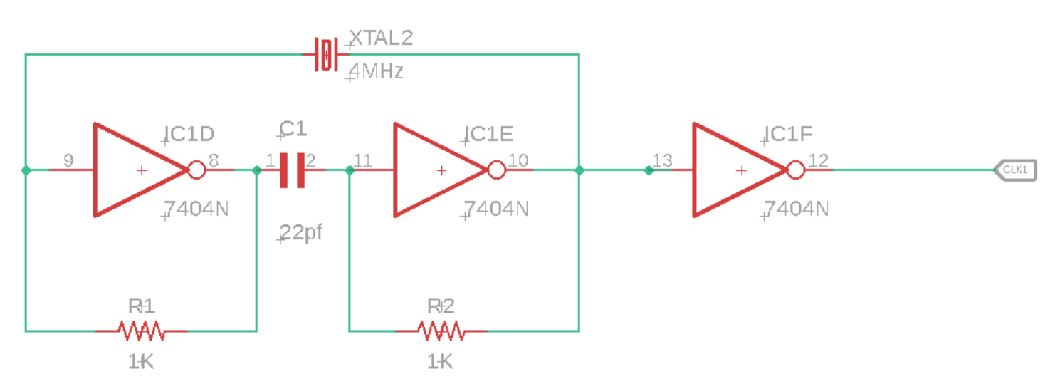
For the clock circuit, I have a 4MHz crystal wired into a circuit with some inverters, resisters, and capacitors. I take the output of that and pass it through another inverter before passing it on to the processor (or the counter between the processor and clock).
For the processor, most of the work is connecting LEDs with resistors to limit the current. Additionally I’ve for the instruction 1 wired to the data bus. With this wired, the only thing the system needs is power.

The Outcome
I’m happy to say that this worked. The processor started running and I can see the address bus values increasing through the LEDs on the most significant bits.
Next Steps
Now that I have the processor in a working state, I want to replace the hard-wired instruction with an EPROM and add RAM. Once I’m confident that all is well with the EPROM and RAM then I’ll add some interfaces for the outside world. While the parts that I think that I’ll need are generally out of production (though there are some derivative processors still available new) used versions are available for only a few dollars. Overall though this is a temporary diversion. Once it is developed to a certain point, it will be shelved, but that’s not the end of my hardware exploration. There are some things I’d like to do with some ARMs processors (likely an STMF32 arm processor). Many of the ARMs processors I’ve looked at are fairly complete system-on-a-chip components and don’t require a lot of hardware to get them to their minimal working state beyond a clean power supply.
Resources
One of the nice things about dabbling in Retro Computing is that there are plenty of sources available for the hardware. If you find this interesting and want to try some things out yourself, here are some resources that may be helpful.
- How to Program and Interface the 6800
- m6800 Assembler Visual Studio Extension
- m6800 Assembler
- M6800 Instruction Set
Mastodon: @j2inet@masto.ai
Instagram: @j2inet
Facebook: @j2inet
YouTube: @j2inet
Telegram: j2inet
Twitter: @j2inet
Posts may contain products with affiliate links. When you make purchases using these links, we receive a small commission at no extra cost to you. Thank you for your support.


