If you need to delete a directory in Windows, the function RemoveDirectory is useful if the directory is empty. If the folder is not empty, you don’t need to implement recursive logic. The shell API function SHFileOperation is likely the function that you want to use. To use this function include the header <shellapi.h>. The SHFileOperation can perform various file operations, but the one we are most interested in is deletion. For those of you looking for something quick to copy-and-paste, here is the code.
Other code that you may encounter might use pointer data types to perform this same task. I tend minimize managing memory myself. Instead of using pointers to characters as strings, I used types from the standard library. std::wstring and std::vector<WCHAR> are used instead. When pointers to data types are needed, std::wstring::c_str() and std::vector<WCHAR>::data() can be used to supply them. The function I provide here accepts the full path to the folder to be deleted as a std::wstring. That path is copied to the std::vector<WCHAR>. In addition to the text data being copied, two nulls are copied to the end of the data. This is a requirement of the SHFileOperation function for our purpose. Appending a L'\0\0' to the end of the std::wstring does not result in those null characters being present when we use std::wstring::c_str() to get a WCHAR pointer to the data.
A SHFILEOPSTRUCT structure must be populated with the parameters needed for the operation that we would like to perform. Setting it to { 0 } at initialization will set all of the fields in the structure to zero. This is great for structures where zero or null values are what one wants to set as the default values. The fields that we do populate are
hwnd – The handle to the owner window. This can be set to NULL.
wFunc – Set to a value for the operation that we want to perform. FO_DELETE is the value to use for deletion.
pFrom – Set to the double – null terminated string containing the path to the folder to be delete
lpszProgressTitle – Set to a title to show in a UI window that shows the progress of the operation
fFlags – flags for various operations. The operations selected here include
FOF_NOCONFIRMATION – don’t ask the user for confirmation
FOF_NOERRORUI – don’t show an error UI if the operation fails
FOF_SILENT – don’t show the UI.
In testing this, my results have generally been success or 0x7c (for invalid name). The invalid name return value was encountered when a directory had already been deleted (in which case the value passed really was not a valid identifier for a directory!).
Posts may contain products with affiliate links. When you make purchases using these links, we receive a small commission at no extra cost to you. Thank you for your support.
I had an idea for an application that would be using some native code, but also needed to be customizable through changing JavaScript. v8 was the first choice for a JavaScript engine to integrate. It is the most popular JavaScript engine. Having modified Chromium before, (V8 is part of the Chromium source code) I thought this would be more of the same procedures that I had followed before. That’s not the case. The last time I worked with this code, it was with Microsoft Visual C/C++. But back in September 2024 the V8 group followed Chromium’s lead and removed support for MSVC. The change makes sense, they wanted to reduce the various compiler nuances and hacks that they had to account for when updating the source code. The old procedure I used was not going to work. I had to figure out how to build V8 again.
Appreciation for the V8 Team
I want to take a moment to thank the V8 team for their effort. I’ve not interacted with them directly myself. But from reading in the Google Group for V8, I’ve seen that they’ve been responsive to questions that others have asked, and I’ve found their responses helpful. If/when I do interact with them directly I want to remember to express my appreciation. If you interact with them, I encourage doing the same.
Why doesn’t Google Just Distribute a Precompiled Version
The first time I used V8, I questioned why Google didn’t just make a precompiled version available. After working in it myself, I can better appreciate why one might not want to do that. There are a log of variations in build options. It simply just isn’t practical.
The Build Script
Because the build procedure is expected to change over time, I’ve made the rare decision to call out the V8 version that I’m working with in the title of this post. This procedure might not work with earlier or later versions of V8. Consider what version of v8 that you wish to build. The more significant the difference in that version number and what I’ve posted here (13.7.9) the higher the chance of this document being less applicable.
As I did with the AWS C++ SDK and the Clang compiler, I wanted to script the compilation process and add the script to my developer setup scripts. The script is in a batch file. While I would have preferred to use PowerShell, the build process from Google uses batch files. Yes, you can call a batch file from PowerShell. But there are differences in how batch files execute from PowerShell vs the command prompt.
Installing the Required Visual Studio Components
If you are building the V8 source code, you probably already have Visual Studio 17 20222 installed with C++ support. You’ll want to add support for the Clang compiler and additional tools. While you could start the Visual Studio installer and select the required components, in my script I’ve included a command to invoke the installer with those components selected. You’ll have to give it permission to run. If you want to invoke this command yourself to handle putting the components in place, here it is.
In addition to the source code, Google makes available a collection of tools and utilities that are used in building V8 and Chromium known as “Depot Tools.” These tools contain a collection of executables, shell scripts, and batch files that help abstract away the differences in operating systems, bringing the rules and procedures to be closer together.
Customizing my Script
For the script that I’ve provided, there are a few variables in it that you probably want to modify. The drive on which the code will be downloaded, the folders into which the code and depot tools will be placed, and the path to a temp folder are all specified in the batch file. I’ve selected paths that result in c:\shares\projects\google being the parent folder of all of these, with the v8 source code being placed in c:\shares\projects\google\v8. If you don’t like paths, update the values that are assigned to drive, ProjectRoot, TempFolder, and DepotFolder.
Running the Script
The Happy Path
If all goes well, a developer opens their Visual Studio Developer Command Prompt, invokes the script, and is presented with the Visual Studio Installer UI a few moments later. The user would OK/Next through the isntaller. After that, the Windows SDK isntaller should present and the user does the same thing. The user could then walk away and when they come back, they should have compiled V8 libraries for debug and release modes for x64 and ARMS64.
A walkthrough of what happens
The script I provided must be run from a Visual Studio Developer command prompt. Administrative level priviledges is not needed for the script, but it will be requested during the application of the Visual Studio changes. Because elevated processes don’t run as a child process of the build script, the script has no way of knowing when the isntallation completes. It will pause when the Visual Studio Installer is invoked and won’t continue until the user presses a key in the command window. Once the script continues, it will download the Windows SDK and invoke the installer. Next, it clones Depot Tools folder from Google. After cloning Depot Tools, the application gclient needs to be invoked at least once. Thsi script will invoke it.
With gclient initialized, it is now invoked to download the V8 source code and checkout a specific version. Then the builds get kicked off. The arguments for the builds could be passed as command line argumens, or they could be placed in a file named args.gn. I’ve placed configuration files for the 4 build variations with this build script.
V8 Hello World
Just as I did with the AWS C++ SDK script, I’ve got a “Hello World” program that doesn’t do anything significant. It’s purpose is to stand as a target for validating that the SDK successfully compiled and that we can link to it. The Hello World source is frp, pme pf the programs that Google provides. I’ve placed it in a Visual Studio project. If you are using same settings that I used in my build script, you will be able to compile this program without making any modifications. Nevertheless, I’ll explain what I had to do.
I made a new C++ Console program in Visual Studio. The program needs to know the folder that has the LIB file and header files. The settings for binding to the C/C++ runtime must also be consistent between the LIB and out program. I will only cover configuring the program for debug mode. Configuring for release will involve different values for a few of the settings.
Right-click on the project and select “Properties.” Navigate to the options C++ -> Command Line on the left On the text box on the right labeled Additional Options enter the argument /Zc:__cplusplus (that command contains 2 underscores). This is necessary because, for compatibility reasons, Visual Studio will report as using an older version of C++. The V8 source code has macros within it that will intentionally cause the compilation to fail if the compiler doesn’t report as having C++ 20 or newer. Now, go to the setting C++ -> Language -> C++ Language Standard. Change it to C++ 20. Go to C++ -> General -> Additional Include Directories. In the drop-down on the right side, select “Edit.” Add a new path. If you’ve used the default settings, the new path will be c:\shares\projects\google\v8\include. Finally, go to C++ -> Linker -> General. For “Additional Library Directories” select the dropdown to click on the “Edit” option. Enter the path c:\shares\projects\google\v8\out\x64.debug.
With those settings applied, if you compile now the compilation will fail. Let’s examine the errors that come abck and why.
Unresolved External Symbols
You might get Unresolved External symbol errors for all of the V8 related functions. Here is some of the error output.
v8monolithlinktest.obj : error LNK2019: unresolved external symbol “class std::unique_ptr> __cdecl v8::platform::NewSingleThreadedDefaultPlatform(enum v8::platform::IdleTaskSupport,enum v8::platform::InProcessStackDumping,class std::unique_ptr>)” (?NewSingleThreadedDefaultPlatform@platform@v8@@YA?AV?$unique_ptr@VPlatform@v8@@U?$default_delete@VPlatform@v8@@@std@@@std@@W4IdleTaskSupport@12@W4InProcessStackDumping@12@V?$unique_ptr@VTracingController@v8@@U?$default_delete@VTracingController@v8@@@std@@@4@@Z) referenced in function main 1>v8monolithlinktest.obj : error LNK2019: unresolved external symbol “public: __cdecl v8::Isolate::CreateParams::CreateParams(void)” (??0CreateParams@Isolate@v8@@QEAA@XZ) referenced in function main
These are because you’ve not linked to the the necessary V8 library. This can be resolved through the project settings or through the source code. I’m going to resolve it through the source code with preprocessor directives. The #pragma comment() preprocessor maco is used to link to LIB files. Let’s link to v8_monolith.lib by placing this somewhere in the cpp files.
#pragma comment(lib, "v8_monolith.lib")
If you compile again, you’ll still get an unresolved externals error. This one isn’t about a V8 function, though.
1>v8_monolith.lib(time.obj) : error LNK2019: unresolved external symbol __imp_timeGetTime referenced in function "class base::A0xE7D68EDC::TimeTicks __cdecl v8::base::`anonymous namespace'::RolloverProtectedNow(void)" (?RolloverProtectedNow@?A0xE7D68EDC@base@v8@@YA?AVTimeTicks@12@XZ)
1>v8_monolith.lib(platform-win32.obj) : error LNK2001: unresolved external symbol __imp_timeGetTime
1>C:\Users\Joel\source\repos\v8monolithlinktest\x64\Debug\v8monolithlinktest.exe : fatal error LNK1120: 1 unresolved externals
The code can’t find the library that contains the function used to get the time. Linking to WinMM will take care of that. We another an other #pragma comment() preprocessor directive.
#pragma comment(lib, "WinMM.lib")
Here’s another compiler error that will be repeated several hundred times.
1>libcpmtd0.lib(xstol.obj) : error LNK2038: mismatch detected for '_ITERATOR_DEBUG_LEVEL': value '0' doesn't match value '2' in v8monolithlinktest.obj
The possible range for _ITERATOR_DEBUG_LEVEL is from 0 to 2 (inclusive). This error is stating that the V8 LIB has this constant defined to 0 while in our code, it is defaulting to 2. We need to #define it in our code before any of the standard libraries are included. It is easiest to do this at the top of the code. I make the following the first line in my source code.
#define _ITERATOR_DEBUG_LEVEL 0
The code will now compile. But when you run it, there are a few failures that you will encounter. I’ll just list the errors here. The code terminates when it encounters one of these errors. You would only be able to observe one for each run. The next error would be encountered after you’ve addressed the previous one. These failures are from the code checking to ensure that your runtime settings are compatible with the compile time settings. Some settings can only be set at compile time. If the V8 code and your code have diffeerent expectations, there’s no way to resolve the conflic. Thus the code fails to force the developer to resolve the issue.
Embedder-vs-V8 build configuration mismatch. On embedder side pointer compression is DISABLED while on V8 side it's ENABLED.

Embedder-vs-V8 build configuration mismatch. On embedder side V8_ENABLE_CHECKS is DISABLED while on V8 side it's ENABLED.
These are also resolved by #define directives before the relevant includes. These values must be also be consistent with values that were used when compiling the V8 library. The lines that resolve these errors follow.
I’ve mentioned a few times values for options within the V8 library. Those values come from the arguments that were passed when V8 was built. Let’s take a look at one of the args.gn files that contains these arguments.
I won’t explain everythin within these settings, but there are a few items to call out.
v8_monolith – this option causes all of the functionality to be compiled into a single lib.
use_custom_libxx – when true, the code will use a custom C++ library from google. When false, the code will use a standard library. Always set this to false.
is_debug – set to true for debug builds, and false for release builds
v8_static_library – When true, the output contains libs to be statically linked to a program. When false, dlls are produced that must be distributed with the program.
Many of these settings have significant or interesting impacts. The details of what each one doesn’t isn’t discussed here. I’m assuming that most people that are reading this are just getting started with V8. The details of each of these build options might not be at the top of your list if you are just getting started. For some of these settings, Google has full page documents on what the settings do. The two most important settings are the v8_monolith and the is_debug setting. v8_monolith will package all of the functionality for v8 in a single large lib. The one I just compiled is about 2 gigabytes. If this option isn’t used, then the developer must makes sure that all of the necessary DLLs for the program are collected and deployed with their program.
Enabling is_debug (especially with a symbol level of 2) let’s you step into the v8 code. Even if you trust that the v8 code works fine, it is convinient to be able to step into v8.
Distributing the Outputs
After you’ve made a build and are happy with it, you want to distribute it to either other developers or archive it for yourself. Since this example makes the monolithic build, the only files that are needed are a single lib file (though very large) and the header files. You can find the V8 libs in in v8\out\x64.release\v8_monolith.lib and v8\out\x64.debug\v8_monolith.lib. Note that these files have the same name and are aonly separated by their folder. When you archive the lib, you may want to archive the args.gn file that was used to make it. It can serve as documentation for a developer using the lib. You also need the include folder from v8\includes. That’s all that you need. Because I might want to have more than one version of the V8 binaries on my computer, I’ve also ensured that the version number is also part of the file path.
Finding Resources
I looked around to try to find a good book on the V8 system, and I can’t find any. It makes sense why there are no such books. It is a rapidly evolving system. The best place I think you will find for support is the V8 Google Groups. Don’t just go there when you need help, it may be good to randomly read just to pick up information you might not have otherwise. There is also v8.dev for getting a great surface level explanation of the system. Note that some of the code in the examples on their site are a bit out-of-date. I tried a few and found that some minor adjustments are needed for some code exables to work.
Posts may contain products with affiliate links. When you make purchases using these links, we receive a small commission at no extra cost to you. Thank you for your support.
When creating an application, if we want our own application to be the topmost window, many UI APIs have a call or setting that we can alter to ensure that is how our window displays. For a client, we were asked to make a third-party application that always appeared on top of other windows. Contacting the application vendor, we found that there was no way to do this within the range of settings that we have access to. Nor was there likely to be a method available on our timelines. This isn’t a serious problem though; we can use some Win32 APIs to alter the window settings ourselves.
This is something that is only to be done as a last resort. Manipulating the internal settings of another application can come with risks. When doing something like this, it should be done with a significant amount of testing. To accomplish this task, we only need to get a handle of the window that we wish to affect and call SetWindowPos with the argument HWND_TOPMOST. That’s the easy part. The less obvious part is how does get their hands on the handle of another window. The FindWindows API can be used to get the handle of a Window based either on the window title or the window class name. For the Notepad application on Windows 10, the name of the window class is simply Notepad. We could also get access to a Notepad window if we use the text string that shows up in its title bar. For flexibility, put this functionality into an application or have it use FindWindow up to 2 times so that I can attempt to find the window by the class name or the title. The value to be used here is passed as a command line parameter. In C++, we end up with an application that has the following source code. The application calls these Windows API in a loop. This allows it to have an effect if the target application hasn’t presented a window or if the application closes and reopens.
// AlwaysOnTop.cpp : This file contains the 'main' function. Program execution begins and ends there.
//
#include <iostream>
#include <Windows.h>

void ShowInstructions()
{
    std::wcout << L"Usage:\rn"
        L"AlwaysOnTop.exe[window - name]\r\n"
        L"[window - name] should be either the\r\n"
        L"window or the name of the window class. " << std::endl;
}

int wmain(int argc, wchar_t** argv)
{
    HWND windowHandle = nullptr;
    std::wstring windowName ;
    if (argc < 2) {
        ShowInstructions();
        return -1;
    }

    windowName = std::wstring(argv[1]);

    while (true)
    {
        windowHandle = NULL;
        while (windowHandle == NULL)
        {
            windowHandle = FindWindow(windowName.c_str(), nullptr);
            if (windowHandle == nullptr)
            {
                windowHandle = FindWindow(nullptr, windowName.c_str());
            }
            if (windowHandle == nullptr)
            {
                Sleep(3500);
            }
        }
        std::wcout << "Window handle found for " <<windowName << " }. \r\nSetting to top most window";
        while (true) {

            SetWindowPos(windowHandle, HWND_TOPMOST, 0, 0, 0, 0, SWP_NOMOVE | SWP_NOSIZE);
            SetForegroundWindow(windowHandle);
            Sleep(7500);
        }
    }
}
I’ve found that native executables tend to set off alarms for a security application that we use. The security application isn’t as sensitive to .Net executables. I have the source code in .Net also. It calls the same Windows APIs in the same order.
using System.Runtime.InteropServices;

namespace AlwaysOnTop.Net
{
    internal class Program
    {
        [DllImport("user32.dll", SetLastError = true)]
        private static extern IntPtr FindWindow(string lpClassName, string lpWindowName);

        [DllImport("user32.dll", SetLastError = true)]
        private static extern bool SetWindowPos(IntPtr hWnd, IntPtr hWndInsertAfter, int X, int Y, int cx, int cy, uint uFlags);


        [DllImport("user32.dll")]
        static extern IntPtr SetFocus(IntPtr hWnd);

        [DllImport("User32.dll")]
        static extern int SetForegroundWindow(IntPtr hWnd);

        // Constants for nCmdShow
        const int SW_HIDE = 0;
        const int SW_SHOW = 5;
        const uint SWP_NOSIZE = 0x0001;
        const uint SWP_NOZORDER = 0x0004;
        const uint SWP_NOMOVE = 0x002;
        const int HWND_TOPMOST = -1;
        static readonly IntPtr HWND_TOP = IntPtr.Zero;


        static void ShowInstructions()
        {
            Console.WriteLine(
@"Usage:

AlwaysOnTop.Net.exe [window-name]

[window-name] should be either the
window name or window class.
"
            );
        }

        static void Main(string[] args)
        {
            if(args.Length < 1)
            {
                ShowInstructions();
                return;
            }
            string windowName = args[0];


            IntPtr windowHandle = IntPtr.Zero;

            while(true)
            {
                while (windowHandle == IntPtr.Zero)
                {
                    windowHandle = FindWindow(windowName, null);
                    if (windowHandle == IntPtr.Zero)
                    {
                        windowHandle = FindWindow(null, windowName);
                    }
                    if(windowHandle == null)
                    {
                        Thread.Sleep(3500);
                    }
                }
                Console.WriteLine($"Window handle found for {windowName}. \r\nSetting to top most window");
                while(true){

                    SetWindowPos(windowHandle,  HWND_TOPMOST, 0, 0, 0, 0, SWP_NOMOVE | SWP_NOSIZE);
                    SetForegroundWindow(windowHandle);
                    Thread.Sleep(7500);
                }
            }
        }
    }
}
For applications where the class of the top-most window is not known, what do we do? I threw together one other application to get that information. With this other application, I would start the application whose information I want to acquire, then run my command line utility, saving the CSV text that it outputs. The name of the application is ListAllWindows.exe (descriptive!). The Win32 function EnumWindows enumerates all top-level windows and passes a handle to them to a callback function. In the callback, I save the window handle. With a window handle, I can call GetWindowClass() function to get the class name as a WCHAR array. This gets packaged as a std::wstring (those are safer).
In the second column of this CSV, the names of the Window classes show along with the path to the executable that they belong to. Oftentimes, an application may have more than one top-level window. Figuring out which don’t to use comes down to experimentation. Be prepared to start the program several times.
Posts may contain products with affiliate links. When you make purchases using these links, we receive a small commission at no extra cost to you. Thank you for your support.
While I’ve generally used Visual Studio for C/C++ projects, I’m introducing Clang to my C-related build chain. Clang is a front end for C languages (C, C++, Objective-C, OpenCL, CUDA). There is some other code that compiles with Clang. Building the compiler yourself also allows you to get access to the lates-and-greatest features. If you are only seeking the pre-built binaries, you can find them here. The Visual Studio installer also has support for installing a build of Clang that is older. Before trying to build Clang yourself, consider if one of these other options is right for you.
I like for setup processes to be easily repeatable and automated. For building Clang, I’ve made a batch file to perform most of the steps for me. For building this C/C++ compiler, I need to use a C/C++ compiler. I used Visual Studio 2022 Community Edition for this. I have successfully completed a set of scripts for building Clang and have made them available on Github. Instead of putting them in their own repository, I’ve made a single repository for such scripts. Since Github doesn’t appear to have a way to organize repositories in folders, I’m trying to minimize the number of new ones I make.
Understanding what this means is probably aided by knowing what LLVM is. LLVM (low-level virtual machine) originally referred to a set of technologies that targeted a language-independent machine specification. The project has grown beyond targeting a virtual machine specification. It provides tools that could help someone create a compiler for their own programming language or a compiler for some specific machine architecture. LLVM-based compilers are available for a wide range of programming languages. I’m installing Clang because some other code library that I wish to use compiles with Clang.
Customize the Installation Settings
Before running the script, some customizations should be considered. The script assumes you wish to build and install Clang on your C: drive. I’ve set a default installation path for c:\shares\clang. Variables for this and other settings are set in the script named ClangDefineEnvironmentVariables.cmd. I’ve also included the URLs to a version of CMake, Ninja, and Python. You may already have these tools installed and in your path. If you don’t want the script to attempt to install these tools, you can comment out the variables InstallCmake and InstallPython. If these are not defined, the script will skip its attempt to install them.
@ECHO OFF
setlocal Enabledelayedexpansion
ECHO Defining environment variables
SET InstallPython=true
SET InstallCmake=false
SET InstallDrive=c:
SET InstallRoot=%InstallDrive%\shares\clang
SET TempFolder=%InstallRoot%\temp
SET MSBUILD_FULL_PATH=C:\Program Files\Microsoft Visual Studio\2022\Community\MSBuild\Current\Bin\amd64\MSBuild.exe
SET CMAKE_SOURCE_URL=https://github.com/Kitware/CMake/releases/download/v4.0.0-rc3/cmake-4.0.0-rc3-windows-x86_64.msi
SET CMAKE_FILE_NAME=cmake-4.0.0-rc3-windows-x86_64.msi
SET PYTHON_URL=https://www.python.org/ftp/python/3.13.2/python-3.13.2-amd64.exe
Run Part1.cmd
Once these are defined, there are two scripts to run. Run the script titled Part1.cmd. The body of this script only has a few of lines.
@ECHO OFF
Copy CLangDefineEnvironmentVariables.cmd + 0-InstallDependencies.cmd Combined.bat
call Combined.bat
del Combined.bat
I combine the environment variables script with the script to install dependencies. I then run that resultant script. If I were to execute these scripts separately, I wouldn’t get the same result. The environment variables in the script CLangDefineEnvironmentVariables.cmd get cleared when the script is finished running. They don’t carry over to the next script. This script will require user interaction. It will download and invoke the installers for Cmake and Python. You’ll need to be at the computer to approve the installation. It will also invoke the Visual Studio installer and automatically select Visual Studio components to add. You will need to approve those, too. Since the script cannot know when these installers have completed their job, it will wait for you to press a key at points before continuing. Once these installations are complete, you’ve completed most of the steps that require user interaction. Close the terminal window and open a new one. This new terminal window will have a different path environment that includes CMake and Python.
Run Part2.cmd
This next script could take a few hours to run. Once invoked, your attention isn’t needed any further. This will be a great time to go out to lunch or go to bed. If all goes well, when you return after this script runs, you will have a working Clang installation.
To run Part2.cmd, open a new terminal window to ensure that the environment variables created by the installations are applicable. Like Part1.cmd, this script combines two scripts and then runs the results. The file that contains the actions performed is 1-BuildClang.cmd.
@echo off
call CLangDefineEnvironmentVariables.cmd
mkdir %InstallRoot%
cd %InstallRoot%
%InstallDrive%
git clone https://github.com/llvm/llvm-project.git
cd llvm-project
git config core.autocrlf false
mkdir build
pushd build
cmake -DLLVM_ENABLE_PROJECTS=clang -G "Visual Studio 17 2022" -A x64 -Thost=x64 ..\llvm
"%MSBUILD_FULL_PATH%" ALL_BUILD.vcxproj /p:Configuration=Release
"%MSBUILD_FULL_PATH%" tools\clang\tools\driver\clang.vcxproj /p:Configuration=Release
mkdir %InstallRoot%\bin
robocopy \build\Debug\bin %InstallRoot%\bin /MIR
"%MSBUILD_FULL_PATH%" clang.vcxproj
Environment Variables
After the build has been run, the executables are there, but they are not added to your path. If you want to add it to your path, run the script CLangDefineEnvironmentVariables.cmd. It will show a variety of folder paths. The path of interest to you is InstallRoot. Within that folder is a subfolder named bin into which all of the executables have been copied. Add that to your path. You will also want to add the linker from Microsoft Visual Studio to your path. The exact location that this is at could vary. But the specific location for your installation can be found in a file that was created by CLangDefineEnvironmentVariables.cmd.
After both of these have been added, if you would like to test out the setup, I’ve got a HelloWorld.cpp with the scripts. In the subfolder, HelloWorld there is a script named build.cmd. Running that will let you know if you’ve successfully set things up.
Terminal Background
In Windows Terminal, I customize the background so that I can quickly recognize which terminal I’m using. For the terminal that I’m using in Clang, I’ve used an LLVM logo. The image that is included in the repository for this script is the same image. Those who customize their Windows Terminals may be interested in using it.
Posts may contain products with affiliate links. When you make purchases using these links, we receive a small commission at no extra cost to you. Thank you for your support.
Representations of time can differ significantly between programming languages. I recently mixed some .Net code and JavaScript code and had to make some conversions between time representations. This code is generally useful and is being placed here for those who find themselves looking for a quick conversion. Let’s jump into the code.
const long DOTNET_JAVASCRIPT_EPOCH_DIFFERENCE = 621_355_968_000_000_000;
static long DotNetDateToJavaScriptTicks(DateTime d)
{
    return (d.Ticks - DOTNET_JAVASCRIPT_EPOCH_DIFFERENCE) / 10_000;
}

static DateTime JavaScriptTicksToDotNetDate(long ticks)
{
    long dticks = ticks * 10_000 + DOTNET_JAVASCRIPT_EPOCH_DIFFERENCE;
    var retVal = new DateTime(dticks );
    return retVal;
}
To test that it was working, I converted from a .Net time to JavaScript ticks and then back to .Net time If all went well, then I should end up with the same time that I started with.
var originalDotNetTime = DateTime.Now.Date.AddHours(15).AddHours(4).AddMinutes(0);
var javaScriptTicks = DotNetDateToJavaScriptTicks(originalDotNetTime) ;
var convertedDotNetTime = JavaScriptTicksToDotNetDate(javaScriptTicks);

if(originalDotNetTime == convertedDotNetTime)
{
    Console.WriteLine("Time Conversion Successful!");
}
else
{
    Console.WriteLine("The conversion was unsuccessful");
}
I ran the code, and it worked! Honestly, it didn’t work the first time because I left a 0 off of 10,000. Adding the underscores (_) to the numbers makes discovering such mistakes easier. Were you to use this code in AWS, note that some values in AWS, such as a TTL field on a DynamoDB table, expect values to be in seconds, not milliseconds. The JavaScript ticks value would have to be divided by 1000 when converted from a .Net time or multiplied by 1000 when being converted back to a .Net time.
Posts may contain products with affiliate links. When you make purchases using these links, we receive a small commission at no extra cost to you. Thank you for your support.
Recently I was trying to work with the AWS C++ SDK. But I encountered problems with linking the .LIBs from the SDK to my project. Amazon provides instructions on compiling the SDK for various environments. I’m specifically am doing so on Windows with Visual Studio. The compilation process can take more than an hour. As I do with all such time-consuming developer setups, I’ve scripted the process. In this case, I’ve scripted the process as a batch file that is meant to be invoked from a Visual Studio 2022 developer prompt with administrative privileges. You can find a copy of the batch file here: https://github.com/j2inet/DevSetup/tree/main/aws-cpp
Compiling: An Easy Step, but a Long Wait
Should you try to run it yourself, there are 4 variables for paths that you may want to alter.
set CloneDrive=c:
set CloneFolder=%CloneDrive%\shares\projects\amazon
set InstallDrive=c:
set InstallFolder=%InstallDrive%\shares\projects\amazon\aws-cpp-sdk-lib
The version of this script that is checked in targets the C: drive. But on the actual machines I’m using, the drives where I have things are the B: drive and the D: drive. The AWS source code for the SDK will be cloned to the CloneFolder. It is then compiled, and the various DLLs, LIBs, and header files will be copied to subdirectories in the InstallFolder. Run the script, then find something else to do. This is going to take a while to run.
The Difference between Static Linking and Dynamic Linking
Projects that use the Shared option also need for the dependent DLLs to be include. Those that use the Static have the functionality included in the same binary. With the Shared version of a project, you’ll need to make sure that you include all of the DLLs on which a project is dependent. If there is a bug fix to functionality in any of the DLLs, you could update only the affected DLLs. For the Static projects you don’t need to worry about ensuring that you’ve copied all of the dependent DLLs. The needed binary code is baked into your EXE. But if there is a bug fix for any of the AWS libraries, you need to redeploy your entire application.
Even if Deploying with Static Linking, Debug with Dynamic Linking
Figuring out this information was a bit of a pain. I couldn’t locate documentation in the AWS C++ SDK that let me know which libraries had dependencies on which other libraries to know what to link to. With dynamic linking, if I miss a library on which there is a dependency, I get an error message stating what is missing. I find this useful and informative. It is more productive to debug with dynamic linking to get access to this information. The alternative, debugging with staticly linked libraries, results in earlier but less informative error messages at compile time. You’ll get a list of which functions and other objects are missing from the linked libraries. But those error messages do not let you know what LIB is needed to get these.
While Amazon provides information on how to only compile a few dependencies, saving compilation time by not compiling libraries you don’t need, I thought it better to compile everything possibly needed up front. While this can take more than an hour, since no attention is needed while the process is running, it takes very little of one’s own time. After compilation of the SDK, the folder c:\shares\projects\amazon\aws-cpp-sdk-lib has 4 folders. These folders contain the DLLs, LIBs, and headers for release and debug mode for static and dynamic linking.
Screenshot of the 4 compiled AWS SDK folders
Hello AWS with Dynamic Linking
After running this script (and waiting an hour or more), this is where the real challenge begins! Let’s start with a minimalistic AWS C++ project. This is the complete source code. When this program is successfully run, it does about nothing. This is a program that exist not to do something, but to fail or succeed at compiling.
If you make a new C++ Console project in Visual Studio and immediately try to compile this, it will fail. Some additional information is needed. Visual Studio needs to know from where to find the #include headers and the LIB referenced in the source code. Right-click on the project, select Properties, and change the following settings.
C/C++ → General → Additional Include Directories
Click on the setting and select “Edit.” Click on the “New Folder” button and enter the path to the Include files. If you’ve left the default values in the script, this will be c:\shares\projects\amazon\aws-cpp-sdk-lib\DebugShared\include. I’m going to assume you are using default values from this point forward. If you are not, be sure to adjust any path that I state.
Linker → General → Additional Library Directories
Click on the Edit button on this setting. In the window that opens, click on the New Folder button. Enter the path c:\shares\projects\amazon\aws-cpp-sdk-lib\DebugShared\bin.
Compile the program now. It should succeed at being compiled. However, if you run the program, it will likely fail. The program is unable to find the DLL that it needs to run. There are a couple ways to address this. You could change the system search path to include the folder where the DLLs are saved. But since release mode and debug mode use different DLLs, I don’t want to do this. Getting back errors on which specific DLLs are missing proved to be useful to me. For now I will copy the needed DLL, aws-cpp-sdk-core.dll, from the path c:\shares\projects\amazon\aws-cpp-sdk-lib\DebugShared\bin to the x64 output folder. Upon running again, you’ll find out that another dll is needed. Rather than let you discover all the DLLs that are needed, I’ll list them here.
aws-c-auth.dll
aws-c-cal.dll
aws-c-common.dll
aws-c-compression.dll
aws-c-event-stream.dll
aws-checksums.dll
aws-c-http.dll
aws-c-io.dll
aws-c-mqtt.dll
aws-cpp-sdk-core.dll
aws-crt-cpp.dll
aws-c-s3.dll
aws-c-sdkutils.dll
If you copy those DLLs to the output folder and run the project, it will now run. In the above, the project is linking to the Shared (dynamic) version of the libraries. Let’s change it to use the Static.
Hello AWS with Static Linking
Right-click on the project and open it’s properties again. Under Linker -> General -> Additional Include Directories, change the value that you entered to c:\shares\projects\amazon\aws-cpp-sdk-lib\DebugStatic\lib. Under C/C++ → General → Additional Include Directories, change the value entered to B:\shares\projects\amazon\aws-cpp-sdk-lib\DebugStatic\include.
Clean the project and recompile it. It is important that you clean the project. If you don’t, it could continue to run the old version (we haven’t actually changed the source code). When you compile the project now, you will get a lot of linker errors. To resolve these, there are several LIB files that you need to link to. I prefer to link to LIB files in source code. One could also do this through the project settings. The project settings method is preferrable when you want to have multiple build definitions. You could setup your project settings to debug using dynamic links to the DLLs and staticly link for release. If you want to link to the libs, right-click on the project, and select “Properties.” Go to Linker → Input → Additional Dependencies. In this setting you can place the name of the LIBs to which you want to link. Note that in the upper-left corner of the window is a drop-down for Configuration. Here, you could select whether the change you are making applies to the Release builds or Debug builds. Though it is beyond the scope of the discussion here, note that the “Configuration Manager” opens an interface where someone can make additional build variations.
Back to the source code. When we did a dynamically linked build, we got error messages about DLLs that needed to be available. For the static build, there are LIB files that correlate to each one of those DLLs. A line with #pragma comment(lib, "lib-name.lib") for each lib that we need to link to. If you make those lines for each of the DLLs that I listed above and compile again, there will be less unresolved external errors. You could work your way through the error list to discover each of the LIBs that is missing. Or, you could just take my word and copy from the following.
With these added, you should now be able to compile and run the program.
I Can Compile! Now What
There is an actual program that I want to share. But the process of compiling the SDK was involved enough (and takes long enough) such that I thought it was worthy of its own post. I have also found that there are some others that have struggled to compile the SDK and have encountered challenges in figuring out how to link. This post also serves to help them out. The next time I mention the AWS C++ SDK, it will likely be to show an application for storing information on various systems to S3.
Posts may contain products with affiliate links. When you make purchases using these links, we receive a small commission at no extra cost to you. Thank you for your support.
It is the year 2025. Come October, Windows 10 will reach end of life. I have some computers running Windows 11. But I also have a few computers running Windows 10 that haven’t been upgraded yet. They haven’t been upgraded because the PC Health Check application tells me the computers don’t meet the requirements for Windows 11. I was surprised the first time that I saw this. The computer’s configuration isn’t on the weak side. It has 160 gigs RAM, a Xeon series processor running in 3.0 GHz, RTX 3090 video. In every version of Windows prior to 11, new Windows releases would generally run on hardware from the previous version of Windows, even if that meant running with diminished experience.
There are two issues on which my computer fails. (Note: When Windows 11 first started rolling out, the upgrade would not give me informative reasons for not installing making the problem even more perplexing). The computer didn’t have a TPM, and the processor isn’t supported. The TPM problem is an easy one to address. I could just buy a TPM for less than 20 USD and plug it into the motherboard. But why the processor wasn’t supported was confusing. But within the past week, I saw a post in the Microsoft Answers forum that, while speculative, gave me a bit of relevant information. I am [re]posting the message in its entirety.
(Speculation with facts…perhaps at least a level frame of reference when explaining ‘why’ to the higher ups when it’s time)
Your unsupported processor(s) are a security risk to MS moving forward. It’s not about speed, or cores, cache size, or anything like that. It’s all about the older architecture.
In 2018 modern CPUs were affected by serious design flaws that enabled the Spectre and Meltdown side channel attacks. Microsoft had to release patches for Windows that slowed down PCs with older CPUs. This let Windows work around the security problems in these processors. A band-aid basically.
As recently as November 2021 Intel confirmed two high severity vulnerabilities concerning almost every flavor of Xeon processor.
Intel (and other CPU manufacturers, to some degree) would totally have to rearchitect their older CPU designs to truly patch these security weaknesses. (…and you know that’s not going to happen)
(The important part here)
Intel said that Spectre and Meltdown were addressed with hardware level changes starting with the Intel 8th-generation CPUs. I find it super interesting that Windows 11 requires 8th-generation CPUs or newer? I imagine this is very related. Of course, Microsoft isn’t screaming from the rooftops that PCs with older CPUs are fundamentally insecure at a hardware level compared to new devices. That wouldn’t be good for business. But it seems like Microsoft wants to quietly move everyone to new hardware so Microsoft knows it only has to support Windows 11 on CPUs with these security fixes.
That’s business I suppose… Hope that helps!
Having read that it may be a security concern but not a capabilities issue, I decided to move forward with trying to upgrade. I purchased a TPM. It showed up the next day. Note that some motherboards have a TPM built in that must be enabled first, or may required a firmware update. After plugging it in, I knew that there was a registry change that I would need to make force the installation. The key is located at HKEY_LOCAL_MACHINE\SYSTEM\Setup\MoSetup. There should be a DWORD value in this location named AllowUpgradesWithUnsupportedTPMOrCPU. Ensure that this element has it’s value set to 1. After this change, I tried to perform the upgrade. It ran without complaint and so far things have been working fine. Having a TPM appears to be the most important feature. Without one, the Windows Installation will not complete.
Should you Try This?
As much as I would love to give you a plain “yes” or “no” answer on this, I can’t. I can understand the position that Microsoft might be in. If this decision is in fact a response to the Spectre bug, then this route is associated with higher security risks. I can’t tell you to take that risk. On the other hand, with Windows 10 security updates coming to an end (unless someone pays for them) raises risks (or costs) with not migrating over. That’s an assessment that you’ll have to make on your own. For more information on the nature of the bug that is speculated to be behind this decision, at least in part, see the Wikipedia entry about it.
Enabling or Acquiring a TPM
You should first check your BIOS/UEFI to see if TPM settings are present within it to be enabled. If there are not any settings, check your motherboard. Many motherboards will have unpopulated sockets in them which are labeled. Search for one labeled TPM. If you find it, take note of pin positions in the socket and whether there are any pins missing. Your motherboard may also be labeled with a manufacturer. In my cases, I found one TPM specifically for Gigabyte motherboards and another generic 20-pin (technically 19, wince one position is blank) for another motherboard. I was able to source my TPMs from Amazon.
I’m working on a project with a Raspberry Pi Pico to control some devices over IR (infrared). Many IR controlled devices pulse the IR LED at a frequency of about 38 kilohertz so that it can be differentiated from other stray IR light sources. What is a good way to turn a pin on and off 38,000 times per second? As a starting point, I used one of the PICO examples that generates a square wave.
The most obvious way would be to write code in a cycle that activates a pin, waits for a moment, and then deactivates a pin. That code would look similar the following.
There are 1,000,000 us (microseconds) in a second. The total of the two waits together is 24 us. 1,000,000/24 is 38,461. There will be additional time consumed on the calls to set the pins, making the actual number of times that this code can run in a loop per second to be slightly lower than 38,461. But it is close enough to be effective.
There is a lot of room for improvement in approach. A significant problem with this code is that it consumes one of the execution cores of the processor to be in wait states. This is a waste of a processor core; there’s other work that it could be doing in that time. Let’s take a step towards a better approach. While there are several elements that would be part of a better solution, I want to focus on one.
In addition to the primary cores, the Pi Pico also has processors that are made specifically for operations on a few of the GPIOs. These make up the Programmable IO (PIO) system. This processor is simple. There are two blocks of 4 processors (8 total). There are only 9 instructions that the processor can execute. But its execution of these instructions is deterministic, taking 1 clock cycle per instruction. We can also set an instruction to wait up to 31 additional cycles before going to the next instruction.
These execution units give a developer the following hardware to work with.
Two general purpose registers, labeled X and Y
An Input and Output shift register
A Clock Divider for modifying the execution speed of the PIO unit
Access to the Pico’s IRQ registers
Mapped and direct access to the GPIO pins
Because the execution units support mapped IO, the same program could run on multiple PIO units and be assigned to different GPIOs
PIO is programmed with PIO Assembler (pioasm). Each PIO unit has two general purpose records, labeled X and Y. There are only 9 instructions, each of which is encoded as a 16-bit structure of the instructions and the operands. We don’t need all the instructions for the task I’m trying to accomplish here. I’ll list all nine of them.
IN – shift up to 32 bits from a GPIO or register to the input shift register
OUT – shift up to 32 bits from the Output Shift Register to a pin or register
PULL – move the contents of the Tx FIFO to the output shift register
PUSH – move the contents of the input shift register to the Rx FIF and clear the ISR.
MOV – Copy data from a register or pin to some other register or pin.
IRQ – Sets or clears an IRQ flag
SET – Write an immediate value to a pin or register
JMP – Jumps to an absolute address within the PIO instruction memory
WAIT – stall execution until a specific pin or IRQ flag is set or unset
Since all I am trying to do is set a pin to alternating states, the only instruction I need for this program is the SET instruction. One call to SET will activate a pin. Another call will deactivate it. The part where more attention must be given to detail is to ensure that this happens about 38,000 times per second. There will be more code in this posting about setting PIO attributes than in the PIO code itself. Let’s address the easier part, the PIO program.
The PIO program itself is only 7 lines. Most of these lines are not executable code. The first line lets the software tools know what version of the pio spec is being used. The second line sets the name of the program. This name will propagate to other auto-generated elements in code. It isn’t only notational. In the third line, I specify that the pins that are assigned to the program should be set to output pins. There will only be one pin assigned to the program.
The first line of executable code is the call to “set pins , 1 [1]”. This sets the assigned pin to high. The [1] next to the instruction causes the execution unit to stall for a clock cycle. This line of code takes 2 clock cycles to execute. The next line sets the pin to the low state.
.pio_version 0
.program squarewave
    set pindirs, 1  ; Set pin to output
loop:
    set pins, 1  [1]
    set pins, 0
    .wrap
The last line of the program, .wrap, marks the end of the executable code. While .wrap isn’t itself an instruction, implicitly there is a JMP instruction hat gets executed when this line is reached. The program will either jump to the beginning of the code (if no jump target is specified) or it will jump to a line with .wrap_target (if such a line is entered). The code that gets executed could be written as follows.
loop:
set pins, 1 [1] ; Set pin (1-cycle) + delay (1-cycle) = 2-cycles
set pine, 0 ; 1-cycle
 jmp loop ; 1-cycle
You might have the question of why I have a delay. I want the output to have a 50% duty cycle. If I wrote that code without any delays, then the pin would be high for 1/3 or the cycle and low for 2/3, since the pin would remain low while the jump instruction was executing.
When the code is compiled, a C++ header file is emitted. The C++ header contains the program as an array of numerical data. It also defines some additional functions that provide support and initialization for the program. If we want additionally C/C++ code that is associated with our PIO program, we can embed C/C++ code in our PIO file. This ensures that if the PIO is distributed, the C/C++ code will always be distributed with it. We just need to ensure that it is embedded between “% c-sdk {“ and “%}”.
For my program, I have added a function named “squarewave_program_init” that performs a few tasks. It performs the some initialization steps for my PIO program, including applying a clock divider to lower the frequency at which the program runs.
We still need to calculate a divider frequency. The Raspberry Pi Pico can run up to 133 MHz. They will generally be clocked between 125 MHz and 133 MHz. To get the frequency at which the Pico is running, we can use the function clock_get_hz(). Each loop of my PIO program needs 4 instructions. To run at 38KHz, I need for the PIO program to run with a clock rate of 38,000 x 4 times per second. The PIO clock rate needs to be at 152 KHz. The divider amount needs to be the result of the clock frequency divided by 152,000.
The last couple of things that must be done is that I need to grab an available PIO unit and assign my program to it. Then I need to enable my program to run.
After that last line of code runs, the PIO will be active and running the program. It will stay active until I deactivate it (or the Pico loses power). If I needed to stop the PIO program and deallocate the use of resources, I can perform that with a call to pio_remove_program_and_unclaim_sm();
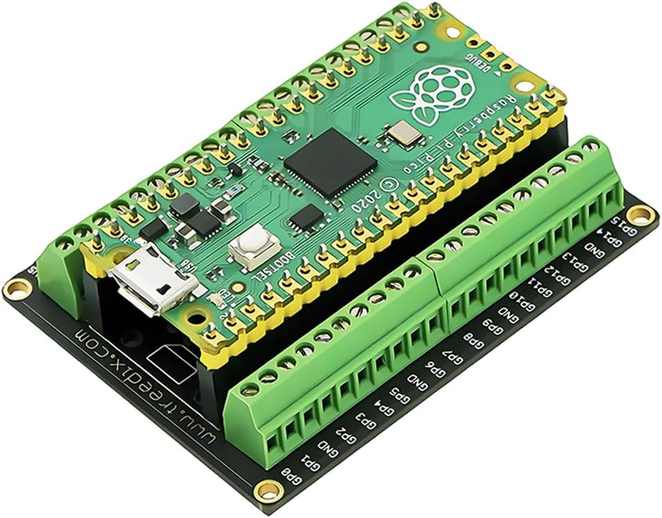
The Pico that I am using is connected to a break-out board that shows the status of each one of the GPIOs. (See A Pi Pico Breakout Board – j2i.net).While 38KHz is too fast to observe with the naked eye, when I run the program, the first indication that it is operating as expected is that the light on the target pin appears to be illuminated with a slightly lower intensity than the other pins. This is expected, since the status light is unpowered 50% of the time.
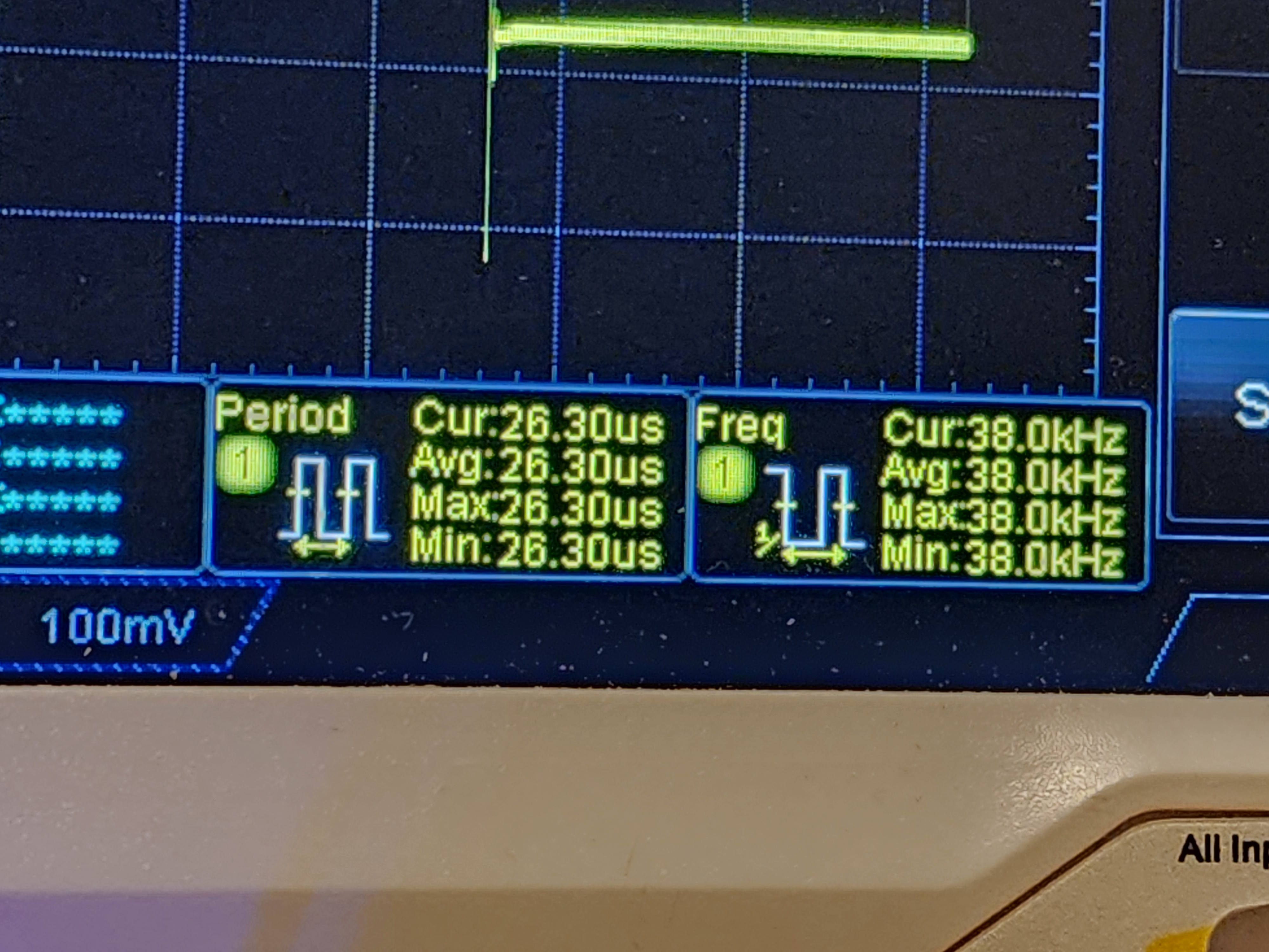
To know it is working, we can use an oscilloscope. Connecting the scope to the pin, I see a square wave.
Checking the frequency on the scope, I see a reading of 38.0 KHz.
This gives me a carrier for IR signalling. With that accomplished, I now need to turn this output on and off in a sequence to communicate an IR message. If you’d like to see the code used for making this post in the form it was in at the time this post was published, you can find it on GitHub at this URL.
Posts may contain products with affiliate links. When you make purchases using these links, we receive a small commission at no extra cost to you. Thank you for your support.
I’ve got a machine that I’ll be repuposing and decided to add additional drives to it. I’ve got plenty of 2.5 inch drives on shelves and through they would be good candidates for the machine. Often times, the limits on how many drives I place in a machine is from how many bays there are to place them; the machines are often capable of connecting to more drives. There is just no place to put them.
The Icy Dock (or flexDOCK) is a solution for this. I’m using a SATA verion. There is a version for M.2 drives also. The Icy Dock distributes power to up to 4 drives (only one power cable is needed to the Dock) and provides 4 slots for holding hot-swappable drives. The device installs into a 5.25 inch bay. Horizontally in line on the back of the dock are 4 SATA connectors; one connector is available for each drive. There is also a fan on the back of the unit for circulating air over the drives. Speed adjustment for the fan is on the front of the dock. There’s a jumper on the back for disabling the fan alltogether.
Provided that the computer’s operating system and firmware supports it, these drives are hot-swappable. If one wants to experiement with different operating systems on the same computer, this is a great option for being able to swap out drives without breaking out a screwdrive or removing drive bays. Each one of the slots for a drive has a power button that can be used to disrupt power from the drive, and an eject button.
One criticism I have is that the eject buttons sometimes require a lot of force to eject the drive. But it is still much easier and more convinient than opening up the drive.
Posts may contain products with affiliate links. When you make purchases using these links, we receive a small commission at no extra cost to you. Thank you for your support.
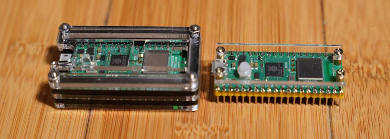
I picked up a few Pi Pico cases. Both provide different protection for the units. I also find them to be aesthetically pleasing additions to have on the board. They both protect the top and underside of the board. The most significant difference is whether they also protect the pins that may be soldered to the board.
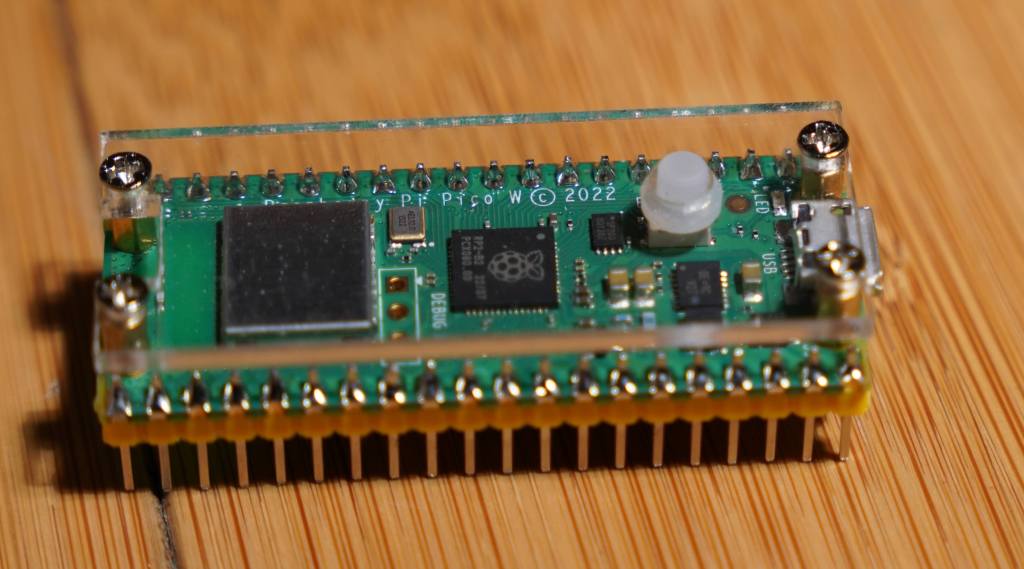
One of the cases is minimalistic. It sandwiches two pieces of acrylic around the board. There are spaces so that the acrylic on the top side isn’t resting on the board and has enough space to hold an extension so that the BOOTSEL button is still accessible. But this case was clearly made for the Picos that don’t have the WiFi chip. The debug header pins are in different places on the Picos with Wi-Fi and without. If you don’t use the debug header pins, this won’t be an issue. The lower acrylic is just wide enough to cover the bottom of the board between the header pins. This case protects the board itself, but not the pins that are connected to it. I use this on a Pico that is connected to a breakout board. That it doesn’t cover the pins gives me enough clearance to easily plug it in.
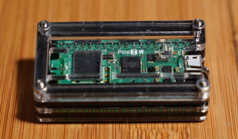
C4Labs Case
C4Labs Case
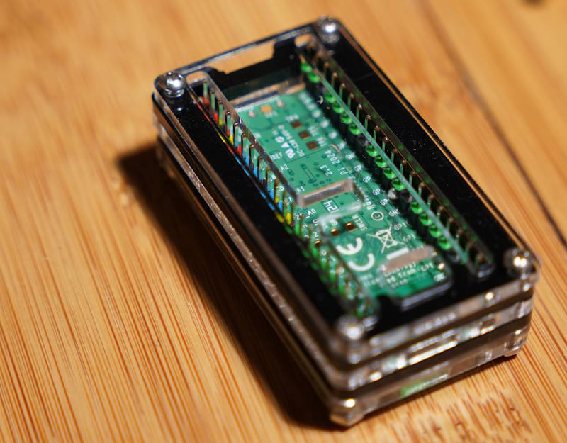
The other case, from C4Labs, is also made of acrylic pieces. Though it is many more pieces sandwiched together to completely envelope the Pico circuit board, the pins, and the debug header. This case was made to universally fit the Picos with and without Wi-Fi. There are cutouts for either position of the debug header. Since the pins are completely enveloped, there are restrictions on how one might connect something to it. Jumper wires will connect to the pins without trouble.
I cannot use this case with the breakout board that I have though. Parts of the case conflict with other connectors that I have on my breakout board. However, the area in the case in which the pins would extend could potentially be used to hold a small amount of other electronics. I’m working on an IR control project, and I might place an IR Emitter and detector within this space.
These cases are available on Amazon. The minimalistic case is available by itself or with a Pi Pico. You can purchase them through the following links. Note that these are affiliate links. I make a small commission if you purchase through these links.
Posts may contain products with affiliate links. When you make purchases using these links, we receive a small commission at no extra cost to you. Thank you for your support.
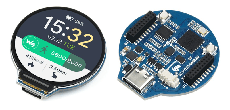
In a previous post, I mentioned that I was re-introducing myself to development for the Pi Pico. The Pico is a microcontroller, often compared to an Arduino, that can be programmed from a Linux, Mac, or Windows machine. The Pico is based on the RP2040 chip. This is an ARM based Cortex-M0 dual core processor, generally running between 125 and 133 MHz. It has 264 KB of SRAM, 2 MB of flash memory, 26 general purpose IO pins, some of which support additional functionality. The other functionality overlaid on these pins includes
2 UART pins
2 SPI controllers
2 I2C controllers
16 PWM channels
There are several development boards that use the RP2040. Collectively, I generically refer to all of these as Pico. It is a bit easier to say then “RP2040 based board.”
I already had a few machines setup for development for the Raspberry Pi Pico. While that procedure still works, as do those development machines, I was recently reintroducing myself to Pico development. I started with a clean installation and went to the currently published instructions for setup. The more recent instructions are a lot easier to follow; there are less dependencies on manually setting paths and downloading files. The easier process is made possible through a Visual Studio Code plugin. This extension, which is still labeled as a zero version at the time that I am making this post (0.17.3) adds project generation and sample code along with scripts and automations for common tasks. To get started, just Install the Raspberry Pi Pico Visual Studio Code Extension. Once it is installed, you’ll have a new icon on the left pane of VS Code for Pico related tasks.
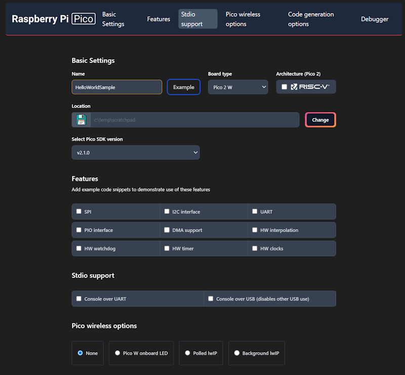
The first time you do anything with this icon, expect it to be slow. It installs the other build tools that it needs on-demand. I prefer to use the C++ build tools. Most of what I write here will be focused on that. I’ll start with creating a new C++ project. Double-clicking on “New C/C++ Project” from the Pico tools panel gets the process started.
This will only be a “Hello World” program. We will have the Pico print a message to a serial port in a loop. The new project window lets us specify our target hardware, including which hardware features that we plan to use. Selecting a feature will result in the build file for the project linking to necessary libraries for that feature and adding a small code sample that access that feature. Select a folder in which the project folder will be created, enter a project name, and check the box labeled “Console over USB.” After selecting these options, click on the “Create” button.
This is the part that takes a while the first time. A notification will show in VS Code stating that it is installing the SDK and generating the project. The wait is only a few minutes. While this is executing, it is a good time to grab a cup of coffee.
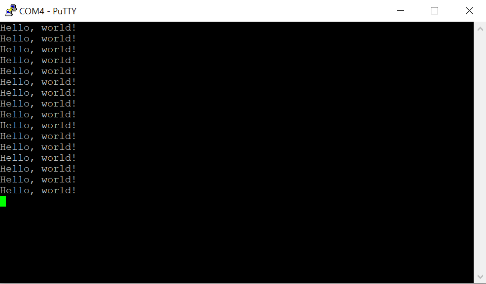
When you get back, you’ll see VS Code welcome you with a new project. The default new project prints “Hello, world!\n” in a loop with a 1 second delay. Grab your USB cable and a Pico. We can immediately start running this program to see if the build chain works. On the Pico, there’s a button. Connect your USB cable to your computer, then connect the Pico, making sure you are holding down this button as you connect it. The Pico will show up on your computer as a writable drive. After you’ve done this, take note of which serial ports show up on your computer. In my case, I’m using Windows, which shows that Com1 is the only serial port. In VS Code, you now have several tasks for your project that you can execute. Double-click on Run Project (USB). The code will compile, deploy to the Pico, and the Pico will reboot and start running the code.
Check to see what serial ports exist on your computer now. For me, there is a new port named Com4. Using PuTTY, I open Com4 at a baud rate of 115,200. The printed text starts to show there.
Using the USB UART for output is generally convenient, but at time you may want to use the USB for other features. The USB output is enabled or disabled in part through a couple of lines in the CMakeList.txt file.
The 1 and 0 can be interpreted as meaning enable and disable. Swap these values and run the project again by disconnecting the Pico, reattach while pressing the button, and then selecting the Run Project (USB) option from VS Code. When you run the code this time, the output is being transmitted over GPIO pins 0 and 1. But how do we read this?
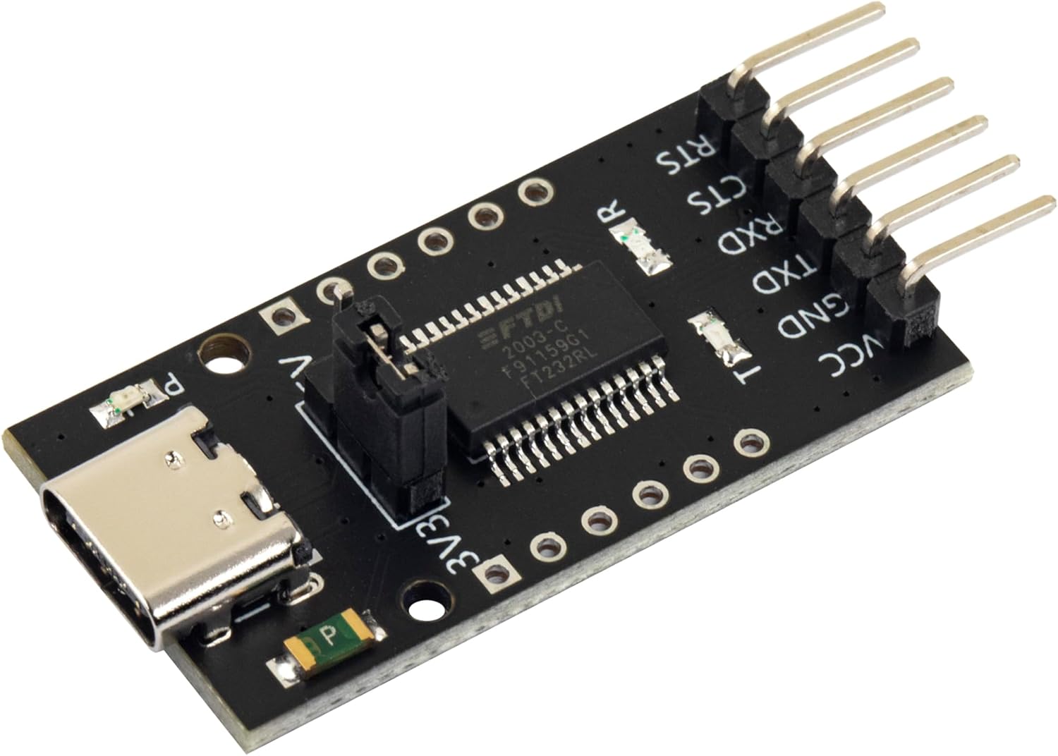
FTDI USB
FTDI is the name of an integrated circuit manufacturer. For microcontroller interfacing, you might often see people refer to “FTDI USB” cables. These are USB devices that have 3 or 4 pins for connecting to other serial devices. These are generally cheaply available. The pins that we care about will be labeled GND (Ground), TX (Transmit), and RX (Receive). The transmit pin on one end of a serial exchange connects to the receive end on the other, and vice versa. On the Pico, the default pins used for uart0 (the name of our serial port) are GP0 for TX and GP1 for RX. When connecting an FTDI device, connect the FTDI’s RX to the Pico’s TX on GPO, then the FTDI’s TX to the Pico’s RX (on GP1), and finally the FTDI’s ground to the Pico’s ground.
GPIO – Setting a Pin
Many, Pico’s have a LED attached to one of the pins that is immediately available for test programs. While many do, not all do. On the Pi Pico and Pi Pico 2, GPIO 25 is connected to a LED. On the Pi Pico W, the LED is connected to the WiFi radio and not the RP2040 directly. For uniformity, I’ll drive an external LED. I’ve taken a LED and have it connected in series with a resistor. 220Ω should be a sufficient value for the resistor. I’m connecting the longer wire of the LED to GP5 and the shorter pin to ground.
In the code, the pin number is assigned to a #define. This is common, as it makes the code more flexible for others that may be using a different pin assignment. Before we can start writing to the pin, we need to gall an initialize function for the pin number named gpio_init(). After the initialization, we need to set the pin to be either in input or output mode. Since we are going to be controlling a LED, this needs to be output mode. This is done with a call to gpio_set_dir() (meaning “set direction”) passing the pin number as the first argument, and the direct (GPIO_IN or GPIO_OUT) as the second argument. For writing, we use GPIO_OUT. With the pin set to output, we can drive the pin to a high or low state by calling gpio_put(). The pin number is passed in the first argument, and a value indicating whether it should be in a high or low state in the second argument. A zero value is considered low, while a non-zero value is considered high. To make it apparent that the LED is being driven by our control of the pin (and not that we just happened to wire the LED to a pin that is always high) we will turn the light on and off once per second. In a loop, we will turn the light on, wait half a second, turn the light off, and wait again.
When we run the code now, we should see the light blink.
Up Next: Programmable IO – The Processor within the Processor
While the GPIO system can be manipulated by the main processor core, there are also smaller processors on the silicon that exist just for controlling the GPIO. These processors have a much smaller reduced set but are great for writing deterministic code that controls the pins. This system of sub-processors and the pins that they control are known as “Programmable IO.” They are programmed using assembler. There’s much to say about PIO. In the next post that I make on the Pico, I’ll walk you through an introduction to the PIO system.
Posts may contain products with affiliate links. When you make purchases using these links, we receive a small commission at no extra cost to you. Thank you for your support.
I’ve used a Pi Pico before. But it has been a while, and I decided to jump back into it in furtherance of some other project I want to do. I’m specifically using a Pico W on a Freenove breakout board. The nice thing about this board is that all the GPIOs have status LEDs that lets you monitor the state of each GPIO visually. For those that might have immediate concern, the LEDs are connected to the GPIO via hex inverters instead of directly. This minimizes the interaction that they may have with devices that you connect to them.
Blinking the Light
About the first program that one might try with any micro controller is to blink a light. I accomplished that part without issue. But for those that are newer to this, I’ll cover in detail. Though I won’t cover the steps of setting up the SDK.
I’ve made a folder for my project. Since I plan to evolve this project to work with an infrared detector, I called my project folder irdetect. I’ve made two files in this folder.
CMakeList.txt – the build configuration file for the project
main.cpp – the source code for the project
For the CMakeList.txt file, I’ve specified that I’m using the C++ 23 standard. This configuration also informs the make process that main.cpp is the source file, and that the target executable name will be irdetect.
cmake_minimum_required(VERSION 3.13)

include(pico_sdk_import.cmake)

project(test_project C CXX ASM)
set(CMAKE_C_STANDARD 11)
set(CMAKE_CXX_STANDARD 23) #Latest C__ Standard available
pico_sdk_init()

add_executable(irdetect
   main.cpp
)

pico_enable_stdio_usb(irdetect 1)
pico_enable_stdio_uart(irdetect 1)
pico_add_extra_outputs(irdetect)
The initial source code for blinking a LED is alternating the state of a random GPIO pin. Since I’m using a breakout board with LEDs for all the pins, I am not restricted to one pin. For the pin I selected, it is necessary to call gpio_init() for the pin, and then set its direction to output through gpio_set_dir(). If you don’t do this, then attempts to write to the pen will fail (speaking from experience!).
#include <stdio.h>
#include "pico/stdlib.h"
#include "hardware/gpio.h"
#include "pico/binary_info.h"
#include "pico/cyw43_arch.h"


const uint LED_DELAY_MS = 250; //quarter second
#ifdef PICO_DEFAULT_LED_PIN
const uint LED_PIN = PICO_DEFAULT_LED_PIN;
#else
const uint LED_PIN = 15;
#endif


// Initialize the GPIO for the LED
void pico_led_init(void) {
	gpio_init(LED_PIN);
	gpio_set_dir(LED_PIN, GPIO_OUT);
}

// Turn the LED on or off
void pico_set_led(bool led_on) {
	gpio_put(LED_PIN, led_on);
}

int main()
{
	stdio_init_all();
	pico_led_init();

	while(true)
	{
		pico_set_led(true);
		sleep_ms(LED_DELAY_MS);
		pico_set_led(false);
		sleep_ms(LED_DELAY_MS);
	}
	return 0;
}
To compile this, I made a subfolder named build inside of my project folder. I’m using a Pico W. When I compile the code, I specify the Pico board that I’m using.
cd build
cmake .. -DPICO_BOARD=pico_w
make
Some output flies by on the screen, after which build files have been deposited into the folder. the one of interest is irdetect.u2f. I need to flash the Pico with this. The process is extremely easy. Hold down the reset button on the Pico while connecting it to the Pi. It will show up as a mass storage device. Copying the file to the device will cause it to flash and then reboot. The device is automatically mounted to the file system. In my case, this is to the path /media/j2inet/RPI-RP2
cp irdetect.u2f /media/j2inet/RPI-RP2
I tried this out, and the light blinks. I’m glad output works, but now to try input.
Reading From a Pin
I want the program to now start off blinking a light until it detects an input. When it does, I want it to switch to a different mode where the output reflects the input. In the updated source I initialize an addition pin and use gpio_set_dir to set the pin as an input pin. I set an additional pin to output as a convenience. I need a positive line to drive the input high. I could use the voltage pin with a resistor, but I found it more convenient to set another GPIO to high and use it as my positive source for now.
#include <stdio.h>
#include "pico/stdlib.h"
#include "hardware/gpio.h"
#include "pico/binary_info.h"
#include "pico/cyw43_arch.h"


const uint LED_DELAY_MS = 50;
#ifdef PICO_DEFAULT_LED_PIN
const uint LED_PIN = PICO_DEFAULT_LED_PIN;
#else
const uint LED_PIN = 15;
#endif
const uint IR_READ_PIN = 14;
const uint IR_DETECTOR_ENABLE_PIN = 13;


// Initialize the GPIO for the LED
void pico_led_init(void) {
        gpio_init(LED_PIN);
        gpio_set_dir(LED_PIN, GPIO_OUT);

        gpio_init(IR_READ_PIN);
        gpio_set_dir(IR_READ_PIN, GPIO_IN);

        gpio_init(IR_DETECTOR_ENABLE_PIN);
        gpio_set_dir(IR_DETECTOR_ENABLE_PIN, GPIO_OUT);
}

// Turn the LED on or off
void pico_set_led(bool led_on) {
        gpio_put(LED_PIN, led_on);
}

int main()
{
        stdio_init_all();
        pico_led_init();
        bool irDetected = false;
        gpio_put(IR_DETECTOR_ENABLE_PIN, true);
        while(!irDetected)
        {
                irDetected = gpio_get(IR_READ_PIN);
                pico_set_led(true);
                sleep_ms(LED_DELAY_MS);
                pico_set_led(false);
                sleep_ms(LED_DELAY_MS);
        }

        while(true)
        {
                bool p = gpio_get(IR_READ_PIN);
                gpio_put(LED_PIN, p);
                sleep_us(10);
        }
        return 0;
}
When I run this program and manually set the pin to high with a resistor tied to an input, it works fine. My results were not the same when I tried using an IR detector.
Adding an IR Detector
I have two IR detectors. One is an infrared photoresistor diode. This component has a high resistance until it is struck with infrared light. When it is, it becomes low resistance. Placing that component in the circuit, I see the output pin go from low to high when I illuminate the diode with an IR flashlight or aim a remote control at it. Cool.
I tried again with a VS138B. This is a three pin IC. Two of the pins supply it with power. The third pin is an output pin. This IC has a IR detector, but instead of detecting the presence of IR light, it detects the presence of a pulsating IR signal provided that the pulsing is within a certain frequency band. The IC is primarily for detecting signals sent on a 38KHz carrier. I connected this to my Pico and tried it out. The result was no response. I can’t find my logic probe, but I have an osciloscope. Attaching it to the output pin, I detected no signal. What gives?
This is where I searched on the Internet to find the likely problem and solutions. I found other people with similar circuits and problems, but no solutions. I then remembered reading something else about the internal pull-up resistors in Arduinos. I grabbed a resistor and connected my input pin to a pin with a high signal and tried again. It worked! The VS138B signals by pulling the output pin to a low voltage. I went to Bluesky and posted about my experience.
I updated my code, and it works! When I attach the detector to the scope, I also see the signal now.
Now that I can read, the next step is to start decoding a remote signal. Note that there are already libraries for doing this. I won’t be using one (yet) since my primary interest here is diving a bit further into the Pico. But I do encourage the use of a third-party library if you are aiming to just get something working with as little effort as possible.
Code Repository
While you could copy the code from above, if you want to grab the code for this, it is on GitHub at the URL https://github.com/j2inet/irdetect/. Note that with time, the code might transition to something that no longer resembles what was mentioned in this post.
Posts may contain products with affiliate links. When you make purchases using these links, we receive a small commission at no extra cost to you. Thank you for your support.
I’m trying out a few things with Raspberry Pi Pico variants, and used a breakout board that I found to be especially convenient. I’m taking a moment to talk about it here and why I liked it. Generally, when I’ve worked with single board computers and Microcontrollers I’ve started off using a breadboard for any circuitry that I wanted to connect to it. There are times when that feels like overkill, such as just when connecting a couple of connectors to the board. In these cases, the breakout board is especially convenient.
When I ordered my boards, I didn’t get all boards of the same type. The board that stands out is one that stands out is from Freenove (affiliate link). There are a few things that make it stand out from the other boards. A small but noticeable convenience is that this board comes with a small screwdriver for the terminal block headers. This board also came fully assembled; many of the other boards ship as a circuit board with components that need to soldered to be usable. The most stand-out feature of the board is that it has status LEDs. There’s a LED for each one of the GPIO pins along with for power and some other signals.
Many microcontroller boards and SBCs have a LED that can be driven by one of the GPIOs, which is great when testing that “Hello World” program and ensuring that your build tools are successful. With the status on other pins, it becomes easier to diagnose otherwise simple programming errors. In one case, I forgot to initialize a pin as an output pin and was able to visually observe that nothing was being written. There was no need to attach the probes to identify what was actually happening.
All of the breakout boards I tried had some form of labelling on the pins. Unfortunately, that text is generally a little too small for me to read. But the Freenove board colors the GPIO and GND labels differently, making it easier to at a glance differentiate between pins. I’ll talk more about one of my experiences in a following post.
Posts may contain products with affiliate links. When you make purchases using these links, we receive a small commission at no extra cost to you. Thank you for your support.
Though I’m aware that a computer can be configured to wake up when it receives a specific LAN packet, I’ve not used the feature until now. I was motivated to do so after a few incidents when I had driven to the office and realized that I had forgotten to push my code from a computer that was at home. It has happened before, in which case I would remote into the computer and perform a push. But a few times that this happened, the computer had already gone to sleep, and I had to persuade someone to press a key on the keyboard to wake it up.
It has happened more than once. I decided it was time to do something about it. The first couple of things that I needed to do were to ensure that the Wake On Lan (WOL) feature was turned on in the BIOS. How this is done may vary from one computer to another. I also needed to get the MAC address for my computer’s active network adapter. Traditionally, WOL has been a feature for wired network adapters only. This is fine for me, since my desktop computers are all on wired connections. From a PowerShell terminal, the MAC addresses for all of the network adapters can be viewed with the command GET-NETADAPTER.The output looks like the following.
PS C:\Users\joel> get-netadapter

Name                      InterfaceDescription                    ifIndex Status       MacAddress             LinkSpeed
----                      --------------------                    ------- ------       ----------             ---------
Bluetooth Network Conn... Bluetooth Device (Personal Area Netw...      11 Disconnected 23-55-D8-7B-36-B1         3 Mbps
Ethernet                  Realtek PCIe GbE Family Controller            7 Disconnected 70-36-BC-23-44-66          0 bps
Wi-Fi                     Intel(R) Wi-Fi 6E AX211 160MHz                5 Up           23-55-D8-7B-36-AD       400 Mbps
The Packet Structure
The structure of the WOL packet is simple. We only need to build this packet and send it over a UDP broadcast message. The packet is 102 bytes in length. The first 6 bytes are just 0xFF repeated 6 times. The rest of the bytes of the packet are the MAC address repeated 16 times. Once the packet is build, it must be sent on a broadcast message. The reason that we send it via a broadcast message is the target computer might not even have an IP address, since it isn’t turned on. Sending it to all computers on a subnet ensures that our target computer will receive the message.
Building Packet in C++
std::vector<BYTE> MacAddressToByteArray(std::wstring macAddress)
{
	std::vector<BYTE> macAddressBytes;
	std::wstring macAddressPart;
	for (size_t i = 0; i < macAddress.size(); i++)
	{
		if (macAddress[i] == L':')
		{
			macAddressBytes.push_back((BYTE)std::stoi(macAddressPart, nullptr, 16));
			macAddressPart.clear();
		}
		else
		{
			macAddressPart.push_back(macAddress[i]);
		}
	}
	macAddressBytes.push_back((BYTE)std::stoi(macAddressPart, nullptr, 16));
	return macAddressBytes;
}


void SendWOL(std::vector<BYTE> macAddress)
{
	std::vector<BYTE> magicPacket;
	for (size_t i = 0; i < 6; i++)
	{
		magicPacket.push_back(0xFF);
	}
	for (size_t i = 0; i < 16; i++)
	{
		for (size_t j = 0; j < macAddress.size(); j++)
		{
			magicPacket.push_back(macAddress[j]);
		}
	}
	BroadcastMessage(magicPacket);
}

void SendWOL(std::wstring macAddress) {
	auto bytes = MacAddressToByteArray(macAddress);
	SendWOL(bytes);
}
Building the Packet in C#
static void SendWOL(IEnumerable<byte> MACAddress)
{
    byte[] packet = new byte[102];
    for (int i = 0; i < 6; i++)
        packet[i] = 0xFF;
    for (int i = 0; i < 102-6; i ++)
    {
        packet[i + 6] = MACAddress.ElementAt(i%6);
    }
    UdpClient client = new UdpClient();
    client.Client.Bind(new IPEndPoint(IPAddress.Any, 0));
    client.Send(packet, packet.Length, new IPEndPoint(IPAddress.Broadcast, 9));
}

static void SendWOL(String MACAddress)
{
    var parts = MACAddress.Split(new char[] { ':', '-' });
    if (parts.Length != 6)
        return;
    byte[] mac = new byte[6];
    for (int i = 0; i < 6; i++)
        mac[i] = Convert.ToByte(parts[i], 16);
    SendWOL(mac);
}

static List<String> GetMacAddressList(String[] args)
{
    List<String> retVal = new List<String>();
    foreach (var arg in args)
    {
        if (MacAddressRegex.IsMatch(arg))
            retVal.Add(arg);
    }
    return retVal;
}
Sending the Packet
The packet must be broadcast on UDP. We use broadcast because the computer doesn’t have an IP address that can be used for sending a unicast message directly to it. It doesn’t matter what port the message is sent on. But we will use Port 9 since many routers are configured to allow UDP traffic on that port. In the C# code, broadcasting the package is simple. It can be be done in three lines.
UdpClient client = new UdpClient();
client.Client.Bind(new IPEndPoint(IPAddress.Any, 0));
client.Send(packet, packet.Length, new IPEndPoint(IPAddress.Broadcast, 9));
The C++ code is using WinSock2 for network communication. Using it is more involved than using the UDPClient object in .Net, but it isn’t complex. We create a datagram socket object, and then enable its broadcast option. We set the target port to 9, and specify its target address is the UDP broadcast address (255.255.255.255). Then we send the data through the port.
I’ve made the executables for both the C++ and the C# code available for download on GitHub. You will find it in the binfolder. There are both signed and unsigned versions available. I made a signed version because one of the computers I intend to use this on is a corporate managed machine that gives less trust to unsigned executables. I can avoid some headaches and paperwork by having a signed executable.
Program Invocation
Not shown in the above source code is that the C++ and C# programs can both accept the MAC address from the command line. Invoking the program with the mac address as the argument to the program will result in it sending a WOL signal to that MAC address. More than one MAC address can be passed to the program.
Posts may contain products with affiliate links. When you make purchases using these links, we receive a small commission at no extra cost to you. Thank you for your support.
I get questions about the case on my iPhone frequently enough such that I thought I would write about it so that I have an answer that I can point people to. The case on my iPhone is different than others in that it is made of metal (aluminum, I believe) and has 1/4 inch threaded screw holes for attaching photo accessories. Without anything additional, I can attach it to a tripod in any of the 4 orientations.
my iPhone in a Cage. Note that the back of the iPhone has a sticker on it that reflects the interior.
The cases I have are for the iPhone 13 and the iPhone 13 Pro. Variations of the cases are available for other iPhones too. Though the cases get redesigns with each iteration and don’t look alike. If you’d like to find one for your phone, here are some links. Note that these are Amazon affiliate links. I earn a small commission if you purchase through one of these links.
Posts may contain products with affiliate links. When you make purchases using these links, we receive a small commission at no extra cost to you. Thank you for your support.