Before your operating system loads, the UEFI (Unified Extensible Firmware Interface) runs. The code in the UEFI is responsible for getting the initial bits of your operating system loaded and then passes control to it for it to load the rest of its components. For the sake of having a better understanding of how things work, this past weekend I decided to write code that would run from the UEFI. Unless you are making system components, this is something that would be impractical to do in the general case. But curious exploration isn’t constrained by practicality. There do exist SDKs for making UEFI programs. Visual Studio also supports the UEFI as a binary target. I’m not using any of the SDKs though. I won’t need them for what I’m doing. To get as far as a “Hello World” I’ll only use Intel Assembler. I wouldn’t suggest that someone that doesn’t already know x86 assembler try this.
Configuring a Visual Studio Project for Assembler
Yes, I’ve not forgotten that I’ve published a video saying that to generally avoid programming in assembler. This isn’t going in any serious code, I don’t have that concern here. From that video, though, I did have instructions on how to create the appropriate type of project in Visual Studio and modify it so that it can compile assembler code.
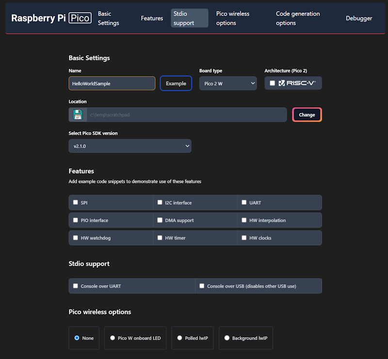
To use Visual Studio for Assembler development, you will want to create a C++ project. C++ projects support mixing C++ and assembly. We will make a C++ project where 0% of the code is in C++ and 100% is in assembly. In Visual Studio you can create an empty C++ project. Add a new file to the project named main.asm. Right now, VS will not do anything useful with that file. There are two changes that must be made. One is that MASM (Microsoft Assembler) targets must be enabled for the project. The other, MASM must be set as the target for your ASM files. To enable MASM as a target first click on your project in the Solution three, then navigate in Visual Studio to the menu selection “Projects” and then “Build Customizations.” Check the box next to “masm(.targets .props)” and click on “OK.”
To set the target type for main.asm you will need to manually update the project file. right-click on your project in the solution tree and select “Unload project.” Search for “main.asm” in the file. You will find a line that looks like this.
<None Include="main.asm" />
Change the word “None” to “MASM” so that it looks like this.
<MASM Include="main.asm" />
Right-click on the project file and select “Reload project.” Visual Studio able to compile now. But it will try to make a Windows application. That’s not what we want. We want a UEFI application. Visual C++ must be set to target UEFI as the subsystem type. Right-click on the project file and select “Properties.” At the top, change the Configuration setting to “All Configurations.” In the settings tree on the left, navigate to Configuration -> Linker -> System. Change the SubSystem setting to “EFI Application.” Now, select the configuration path Configuration -> Linker -> Advanced. Here, set the “Entry Point” setting to “main”, set “Randomize Base Address” to “No”, and set “Data Execution Prevention” to “No”.
Visual Studio will produce an executable that is the same name as the project but with the EXE extension. That’s not what we want. We want the file name to be BOOTX64.efi. To set that, navigate to the settings path Configuration->Linker->General. Change the Output File setting from $(OutDir)$(TargetName)$(TargetExt) to $(OutDir)BOOTX64.efi. With that, all the configuration steps are complete. Now, we need to write code.
Creating our First Program
This first program will be incredibly simple. It does nothing but loop for some number of cycles and then it terminates. That’s it. Why make a program so simple? Debugging is a little more complex for EFI programs and won’t be covered here. In the absence of a debugger, we will make a program that is as simple as possible while also having effect so that it is known that the program ran. Without relying on any external functionality, the most observable thing that the program can do is take up execution cycles. I do this with the assembler equivalent of
for(auto i=0;i<0x1000000;++i)
{
}
While the program is running, the screen is black. When it finishes running, the UEFI will take over. I can run the program with larger or smaller values in the loop to observe longer or shorter periods of time with a black screen, letting me know that it ran. Here is the source code.
.DATA
; no data
.CODE
main PROC
     MOV RCX, 01000000000H
delay_loop:
	DEC RCX
	JNZ delay_loop
	XOR RAX, RAX
	RET
main ENDP
This code loads a register with a large number. It then loops, decrementing the register value and continuing to do so until that register value has reached zero. When it has, the program sets the RAX register to zero and returns control to the UEFI. The UEFI might check the value of RAX since it is set to a non-zero value if a problem occurred. Compile this and copy the output to a USB key in the folder /EFI/BOOT. It is ready to run!
Running the Program
Usually in Visual Studio, you just press [F5] and your program will compile and run. That’s not an option here. The program must be in a pre-boot environment to run. The easiest way to run the code is either from another computer or from a virtual machine. Attempting to run it on your development machine would mean that you would need to reboot. An emulator or a second machine lets you avoid that. I’m using VM Ware Workstation, which is now available for free from VMWare’s site. ( https://www.vmware.com/products/desktop-hypervisor/workstation-and-fusion ). In any case, you’ll want to ensure that “Secure Boot” is turned off. If Secure Boot is turned on, the computer will refuse to run your code because it isn’t signed with keys that the computer trusts. In VMWare Workstation, right-click on the VM that you plan to use for testing and select “Settings.” In the two tabs at the top of the window that appears, select “Options” and then select “Advanced.” Ensure the firmware type is set to UEFI and that “Secure Boot” is not checked. Click on Okay.

Power-On the Virtual Machine. Once it is powered on, In the “VM” menu select “Removable Devices.” You should see your USB drive. Select it and choose the “Connect Option.” The drive will appear to be unplugged from your computer and connected to the host machine.

Now select the option to reboot the VM.

When the machine reboots, you should see the screen remain black for a bit before the UEFI menu shows. During this period when it is black, the program is looping. If you shut down the VM then the USB drive will become visible to your computer again.
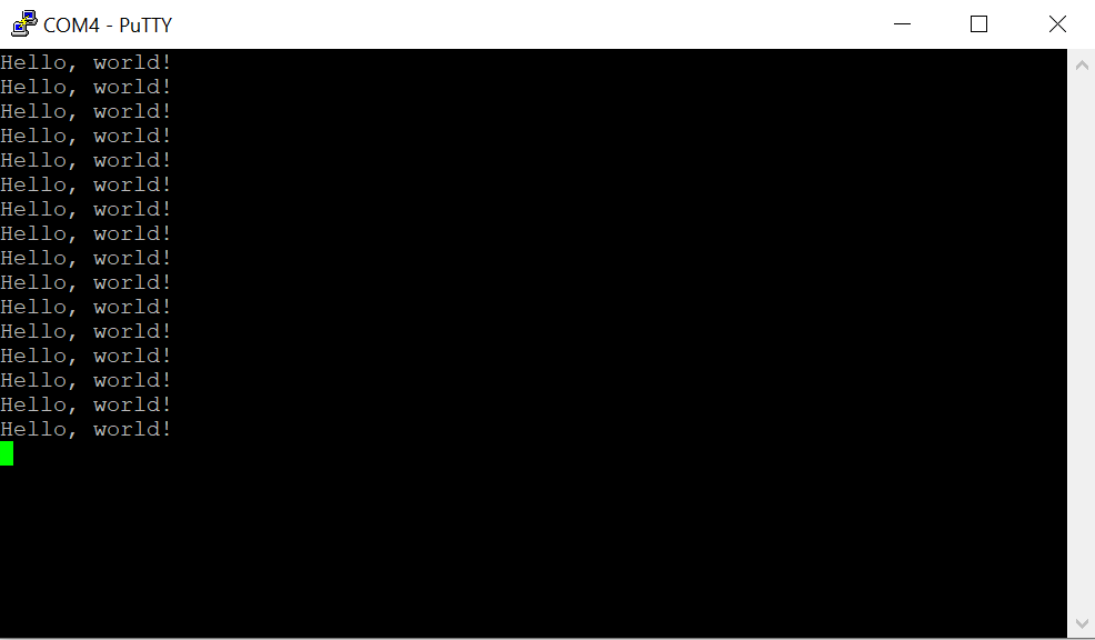
Writing Text
The UEFI has APIs available for reading and writing text, graphics, and more. Let’s try to write text to the screen. We will write “Hello World”, delay, and then return control to the system. This first time that we do that we will be applying knowledge that is known about the system that cannot be inferred from looking at the code alone. When our program starts, two registers already have pointers to a couple of items of information that we need. The RCX register (64-bit general purpose register) has a handle to some Image information. The RDX register has a pointer to the System Table. The system table contains pointers to objects and functions that we will want to use and provides other information about the system. At an offset 0x40 (64) bytes into the system table is a pointer to an object known as ConOut that is used for writing text to the console. At an offset 0x8 bytes from that object’s address is a pointer to the function entry point for the function known as OutputString. We want to call that to display text on the screen. When we call this function, we need to set the RDX register to point to the address of the string that we want to print. After we print, we run our delay and then return control to the UEFI.
.DATA
     szHelloWorld DW 'H','e','l','l','o',' ','W','o','r','l','d','\r','\n', 0
.CODE
main PROC
	SUB RSP, 10H*8
	MOV RCX, [RDX + 40H] ; Get ConOut function address
	LEA RDX, [szHelloWorld]
	CALL QWORD PTR [RCX + 08H] ;Output String
	MOV RCX, 01000000000H
delay_loop:
	DEC RCX
	JNZ delay_loop
	ADD RSP, 10H*8
	XOR RAX, RAX
	RET
main ENDP

END
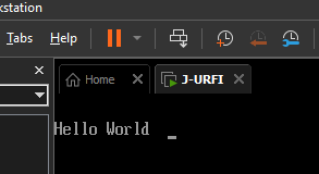
If we run the program now, it shows text
Adding Structures for Reading Objects
Reading data from arbitrary offsets both work and results in horrible readability. The code will be a lot more readable if we read it using structs instead of arbitrary memory offset. There are three structs that we need: EFI_TABLE_HEADER, SYSTEM_TABLE, and TEXT_OUTPUT_INTERFACE.The EFI_TABLE_HEADER here is being used within the SYSTEM_TABLE struct. I could have defined it in line with SYSTEM_TABLE, but it is used by some other UEFI structures. I decided against it. Most of the other entries in the SYSTEM_TABLE are 64-bit pointers (DQ – or double quads, meaning 8 bytes). Though a few members are doubles (DD – or 32-bit numbers).
EFI_TABLE_HEADER STRUCT
  Signature		DQ ?
  Revision		DD ?
  HeaderSize	DD ?
  CRC			DD ?
  Reserved		DD ?
EFI_TABLE_HEADER ENDS

SYSTEM_TABLE STRUCT
	HDR						EFI_TABLE_HEADER <?> ; 00H
	FIRMWARE_VENDOR_PTR		DQ ? ; 18H
	FIRMWARE_REVISION_PTR	DQ ? ; 20H
	CONSOLE_INPUT_HANDLE	DQ ? ; 28H
	ConIn					DQ ? ; 30H
	CONSOLE_OUTPUT_HANDLE	DQ ? ; 28
	ConOut					DQ ? ; 30
	StandardErrorHandle		DQ ? ; 38
	STD_ERR					DQ ? ; 40
	RuntimeServices			DQ ? ; 48
	BootServices			DQ ? ; 50
	NumberOfTableEntries	DD ? ; 58H
	ConfigurationTable		DQ ? ; 60H
SYSTEM_TABLE ENDS

TEXT_OUTPUT_INTERFACE STRUCT
	Reset				DQ	?
	OutputString		DQ	?
	TestString			DQ	?
	QueryMode			DQ	?
	SetMode				DQ	?
	SetAttribute		DQ	?
	ClearScreen			DQ	?
	SetCursorPosition	DQ	?
	EnableCursor		DQ	?
	Mode				DQ	?
TEXT_OUTPUT_INTERFACE ENDS
With these structs defined, there are a few ways we now have access to access structured data. When using a register to access a field of a struct, I can specify the field offset in the MOV operation. The line of code looks like this.
[RDX + SYSTEM_TABLE.ConOut]
Adding that notation to the code, I end up with code that looks like this.
.CODE
main PROC
	SUB RSP, 10H*8
	MOV RCX, [RDX + SYSTEM_TABLE.ConOut] ; Get ConOut function address
	LEA RDX, [szHelloWorld]
	CALL QWORD PTR [RCX + TEXT_OUTPUT_INTERFACE.OutputString] ;Output String

	MOV RCX, 01000000000H
delay_loop:
	DEC RCX
	JNZ delay_loop
	ADD RSP, 10H*8
	XOR RAX, RAX
	RET
main ENDP
Reading Text
For someone that wants to play with this, it may also be helpful to be able to read text from the keyboard. Just as there is a Console Output object, there is also a Console Input object. I’ll have the code wait in a spin-loop until a key is pressed. Then it will print the key that was pressed, delay a bit, and terminate. The UEFI boot services do offer a function that will wait on system events. A key press counts as a system event. But I will stick with a spin-wait for simplicity.
I’m declaring a new procedure named waitForKey. This procedure uses a system object that implements the TEXT_INPUT_PROTOCOL. The object has the method ReadKeyStroke that communicates either that there is no keystroke available (sets the RAX register to a non-zero value) or that there is a keystroke (sets RAX register to zero) and writes the keyboard scan code and Unicode character to the memory address that it received in the RDX register. My code loops while RAX is set to non-zero.
.DATA
     szKeyRead DW ' '
.CODE
waitForKey PROC
		SUB RSP, 8
	waitForEnter_Retry:
		MOV RCX, [systemTable]
		MOV RCX, [RCX + SYSTEM_TABLE.ConIn]
		MOV RDX, RSP
		CALL QWORD PTR [ECX+TEXT_INPUT_PROTOCOL.ReadKeyStroke]
		CMP EAX, 0
		JNZ waitForEnter_Retry
		MOV AX, WORD PTR [RSP+2]
		MOV WORD PTR [szKeyRead], AX
		ADD RSP, 8
		RET
waitForKey ENDP
I’ll put the code necessary to print a string in a procedure, too. It will be called printString. The address to the zero-terminated string must be passed in the RAX register.
printString PROC
		MOV RCX, [systemTable]
		MOV RCX, [RCX + SYSTEM_TABLE.ConOut]
		MOV RDX, RAX
		CALL QWORD PTR [RCX+TEXT_OUTPUT_INTERFACE.OutputString]
		RET
printString ENDP
The code will now wait on user input before terminating.
Downloading the Code
If you want to try this out, the Visual Studio project and source code are available on GitHub. In that repository there is also a build folder that contains the binary. If you want to try it out, copy it to the path efi/BOOT on a FAT32 formatted USB drive and boot from it.
Other Resources
I used VMWare for a test device. It is available for free download from the VMWare Workstation web site. For development, I used Microsoft Visual Studio 2022. It is available for free from the Microsoft Visual Studio website. Information about the various objects that are available for use in UEFI code can be found on the site UEFI.org,
Posts may contain products with affiliate links. When you make purchases using these links, we receive a small commission at no extra cost to you. Thank you for your support.
Mastodon: @j2inet@masto.ai
Instagram: @j2inet
Facebook: @j2inet
YouTube: @j2inet
Telegram: j2inet
Bluesky: @j2i.net