Rediscovering Pi Pico Programming with an IR Detector

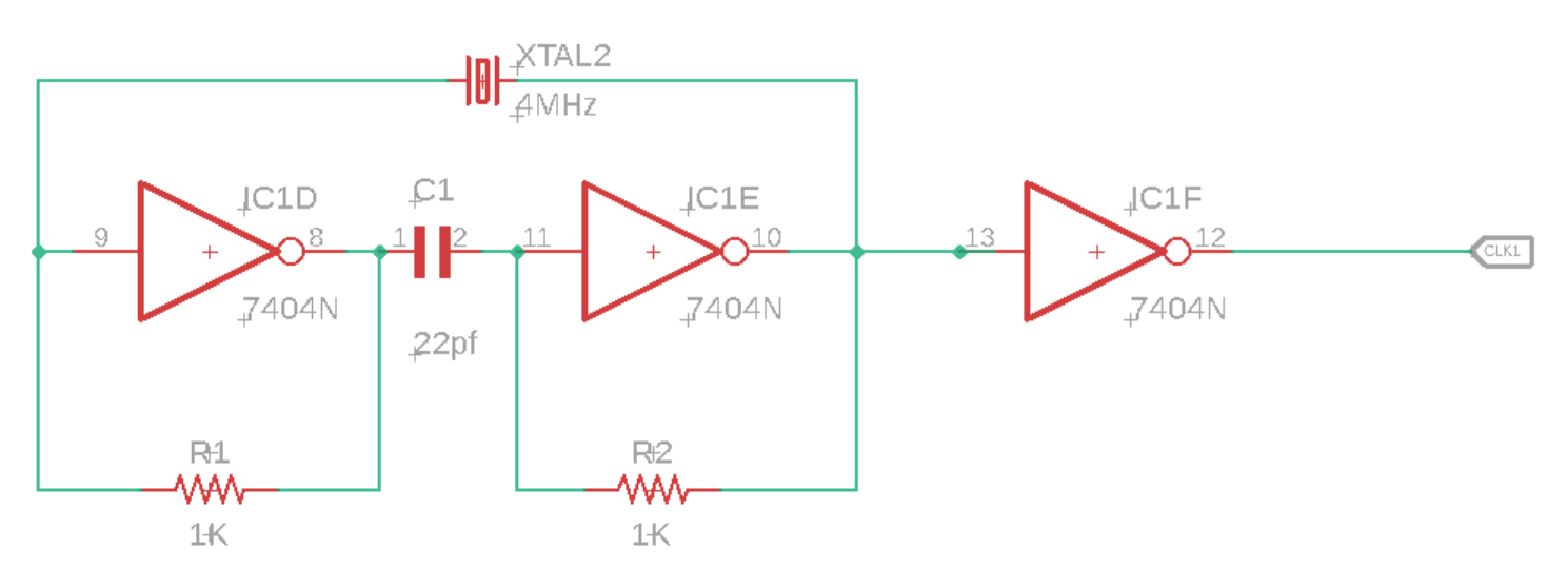
I’ve used a Pi Pico before. But it has been a while, and I decided to jump back into it in furtherance of some other project I want to do. I’m specifically using a Pico W on a Freenove breakout board. The nice thing about this board is that all the GPIOs have status LEDs that lets you monitor the state of each GPIO visually. For those that might have immediate concern, the LEDs are connected to the GPIO via hex inverters instead of directly. This minimizes the interaction that they may have with devices that you connect to them.

Blinking the Light

About the first program that one might try with any micro controller is to blink a light. I accomplished that part without issue. But for those that are newer to this, I’ll cover in detail. Though I won’t cover the steps of setting up the SDK.

I’ve made a folder for my project. Since I plan to evolve this project to work with an infrared detector, I called my project folder irdetect. I’ve made two files in this folder.

  • CMakeList.txt – the build configuration file for the project
  • main.cpp – the source code for the project

For the CMakeList.txt file, I’ve specified that I’m using the C++ 23 standard. This configuration also informs the make process that main.cpp is the source file, and that the target executable name will be irdetect.

cmake_minimum_required(VERSION 3.13)

include(pico_sdk_import.cmake)

project(test_project C CXX ASM)
set(CMAKE_C_STANDARD 11)
set(CMAKE_CXX_STANDARD 23) #Latest C__ Standard available
pico_sdk_init()

add_executable(irdetect
   main.cpp
)

pico_enable_stdio_usb(irdetect 1)
pico_enable_stdio_uart(irdetect 1)
pico_add_extra_outputs(irdetect)

The initial source code for blinking a LED is alternating the state of a random GPIO pin. Since I’m using a breakout board with LEDs for all the pins, I am not restricted to one pin. For the pin I selected, it is necessary to call gpio_init() for the pin, and then set its direction to output through gpio_set_dir(). If you don’t do this, then attempts to write to the pen will fail (speaking from experience!).

#include <stdio.h>
#include "pico/stdlib.h"
#include "hardware/gpio.h"
#include "pico/binary_info.h"
#include "pico/cyw43_arch.h"


const uint LED_DELAY_MS = 250; //quarter second
#ifdef PICO_DEFAULT_LED_PIN
const uint LED_PIN = PICO_DEFAULT_LED_PIN;
#else
const uint LED_PIN = 15;
#endif


// Initialize the GPIO for the LED
void pico_led_init(void) {
	gpio_init(LED_PIN);
	gpio_set_dir(LED_PIN, GPIO_OUT);
}

// Turn the LED on or off
void pico_set_led(bool led_on) {
	gpio_put(LED_PIN, led_on);
}

int main()
{
	stdio_init_all();
	pico_led_init();

	while(true)
	{
		pico_set_led(true);
		sleep_ms(LED_DELAY_MS);
		pico_set_led(false);
		sleep_ms(LED_DELAY_MS);
	}
	return 0;
}

To compile this, I made a subfolder named build inside of my project folder. I’m using a Pico W. When I compile the code, I specify the Pico board that I’m using.

cd build
cmake .. -DPICO_BOARD=pico_w
make

Some output flies by on the screen, after which build files have been deposited into the folder. the one of interest is irdetect.u2f. I need to flash the Pico with this. The process is extremely easy. Hold down the reset button on the Pico while connecting it to the Pi. It will show up as a mass storage device. Copying the file to the device will cause it to flash and then reboot. The device is automatically mounted to the file system. In my case, this is to the path /media/j2inet/RPI-RP2

cp irdetect.u2f /media/j2inet/RPI-RP2

I tried this out, and the light blinks. I’m glad output works, but now to try input.

Reading From a Pin

I want the program to now start off blinking a light until it detects an input. When it does, I want it to switch to a different mode where the output reflects the input. In the updated source I initialize an addition pin and use gpio_set_dir to set the pin as an input pin. I set an additional pin to output as a convenience. I need a positive line to drive the input high. I could use the voltage pin with a resistor, but I found it more convenient to set another GPIO to high and use it as my positive source for now.

#include <stdio.h>
#include "pico/stdlib.h"
#include "hardware/gpio.h"
#include "pico/binary_info.h"
#include "pico/cyw43_arch.h"


const uint LED_DELAY_MS = 50;
#ifdef PICO_DEFAULT_LED_PIN
const uint LED_PIN = PICO_DEFAULT_LED_PIN;
#else
const uint LED_PIN = 15;
#endif
const uint IR_READ_PIN = 14;
const uint IR_DETECTOR_ENABLE_PIN = 13;


// Initialize the GPIO for the LED
void pico_led_init(void) {
        gpio_init(LED_PIN);
        gpio_set_dir(LED_PIN, GPIO_OUT);

        gpio_init(IR_READ_PIN);
        gpio_set_dir(IR_READ_PIN, GPIO_IN);

        gpio_init(IR_DETECTOR_ENABLE_PIN);
        gpio_set_dir(IR_DETECTOR_ENABLE_PIN, GPIO_OUT);
}

// Turn the LED on or off
void pico_set_led(bool led_on) {
        gpio_put(LED_PIN, led_on);
}

int main()
{
        stdio_init_all();
        pico_led_init();
        bool irDetected = false;
        gpio_put(IR_DETECTOR_ENABLE_PIN, true);
        while(!irDetected)
        {
                irDetected = gpio_get(IR_READ_PIN);
                pico_set_led(true);
                sleep_ms(LED_DELAY_MS);
                pico_set_led(false);
                sleep_ms(LED_DELAY_MS);
        }

        while(true)
        {
                bool p = gpio_get(IR_READ_PIN);
                gpio_put(LED_PIN, p);
                sleep_us(10);
        }
        return 0;
}

When I run this program and manually set the pin to high with a resistor tied to an input, it works fine. My results were not the same when I tried using an IR detector.

Adding an IR Detector

I have two IR detectors. One is an infrared photoresistor diode. This component has a high resistance until it is struck with infrared light. When it is, it becomes low resistance. Placing that component in the circuit, I see the output pin go from low to high when I illuminate the diode with an IR flashlight or aim a remote control at it. Cool.

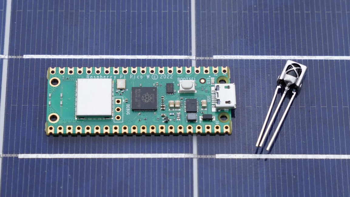
I tried again with a VS138B. This is a three pin IC. Two of the pins supply it with power. The third pin is an output pin. This IC has a IR detector, but instead of detecting the presence of IR light, it detects the presence of a pulsating IR signal provided that the pulsing is within a certain frequency band. The IC is primarily for detecting signals sent on a 38KHz carrier. I connected this to my Pico and tried it out. The result was no response. I can’t find my logic probe, but I have an osciloscope. Attaching it to the output pin, I detected no signal. What gives?

This is where I searched on the Internet to find the likely problem and solutions. I found other people with similar circuits and problems, but no solutions. I then remembered reading something else about the internal pull-up resistors in Arduinos. I grabbed a resistor and connected my input pin to a pin with a high signal and tried again. It worked! The VS138B signals by pulling the output pin to a low voltage. I went to Bluesky and posted about my experience.

https://bsky.app/profile/j2i.net/post/3lgar7brqfs2n

Someone quickly pointed out to me that there are pull-up resistors in the Pi Pico. I just must turn them on with a function call.

those can be activated at runtime:gpio_pull_up (PIN_NUMBER);This works even for the I2C interface.

Abraxolotlpsylaxis (@abraxolotlpsylaxis.bsky.social) 2025-01-21T12:18:18.964Z

I updated my code, and it works! When I attach the detector to the scope, I also see the signal now.

Now that I can read, the next step is to start decoding a remote signal. Note that there are already libraries for doing this. I won’t be using one (yet) since my primary interest here is diving a bit further into the Pico. But I do encourage the use of a third-party library if you are aiming to just get something working with as little effort as possible.

Code Repository

While you could copy the code from above, if you want to grab the code for this, it is on GitHub at the URL https://github.com/j2inet/irdetect/. Note that with time, the code might transition to something that no longer resembles what was mentioned in this post.


Posts may contain products with affiliate links. When you make purchases using these links, we receive a small commission at no extra cost to you. Thank you for your support.

Mastodon: @j2inet@masto.ai
Instagram: @j2inet
Facebook: @j2inet
YouTube: @j2inet
Telegram: j2inet
Bluesky: @j2i.net

Erasing an EPROM with Alternative Devices

I’ve come into possession of an EPROM and got a programmer for it. Writing data to it was easy. Erasing data is another matter. Note that I said EPROM and not EEPROM. What’s the difference? An The first E in EEPROM means “Electrically.” And Electrically Erasable Read Only Memory can be cleared by using some electric circuit. The EPROM I have must be erased through UV light. There is a window on the ceramic package that exposes the silicon underneath. With enough UV light through this window, this chip should be erased.

There are devices sold to specifically erase such memory. I’m not using those. Instead, I have a number of other UV sources to test with. These are

  • The Sun
  • A portable UV phone Cleaner
  • A Clamshell UV Phone Cleaner
  • A Tube Blacklight

I’m using a M27C256 32k EPROM. To know whether my attempt at erasing worked or not I needed to first put something on it. I filled the memory with binary digits counting from 0 to 255, repeating the sequence when I reached the end. The entire 32K was filled with this pattern. To produce a file with the pattern I wrote a few lines of code.

// See https://aka.ms/new-console-template for more information
byte[] buffer = new byte[0x7FFF];
for(int i = 0;i <buffer.Length;i++)
{
    buffer[i] = (byte)i;
}
using (FileStream fs = new FileStream("content.bin", FileMode.Create, FileAccess.Write))
{
    fs.Write(buffer, 0, buffer. Length);
}

Now to get the resultant file copied to the EPROM. The easiest way to do that is with a dedicated EPROM programmer. They are relatively cheap, easy to find, and versatile. I found one on Amazon that worked well for me. Using it was only a matter of selecting what type of EPROM I was using, selecting a file containing the content to be written, and selectin the program button.

The software for writing information to the EPROMs

Reading from the EPROM is just as simple. After the EPROM is connected to the programmer and the EPROM model is selected in the software, it provides a READ button that copies all the bytes from the memory device and displays them in the hex editor. To determine whether the EPROM had been erased I will use this functionality. Now that I have a way to read and write from the EPROM, let’s test the different means of erasure.

Using the Sun

These results were the most disappointing. After having an EPROM out for most of the day, the ROM was not erased. Speaking to someone else, I was told that it would take several days of exposure to erase the EPROM. I chose not to leave the EPROM out for this long, as I’d risk forgetting it was out there when the weather becomes more wet.

Using a Portable UV Sanitizer

The portable UV Sanitizer that I tried was received as a Christmas gift at the end of 2022. Such devices are widely available now in the wake of COVID. This unit charges with a USB cable and runs off of a battery. When turned on, it stays on until it is either turned off, the battery goes dead, or someone turns it over. This unit will only emit light when the light is facing downward. I speculate this is a safety feature; you won’t want to look directly into the EV light.

My first attempts to erase one of the EPROMs with this sanitizer were not successful. After several sessions, the EPROMs still had their data on them. While I wouldn’t look directly into the UV light I could point my camera at it safely. The picture was informative. The light had a brighter level on the end that was closer to the power source, and was very dim at the end. Before, I was only ensuring the window of the EPROM were under some portion of the lighting tube. Now, I knew to ensure it was close to the brighter end of the UV emitter. Using the new placement, I was able to erase an EPROM in about 60 minutes.

UV Sanitizer with the EPROM at the brighter end.

Provided that someone is only erasing a single EPROM and isn’t in a hurry, I think that this could make for an adequate solution for erasing an EPROM. If there’s more than one though his might not work as well, especially when one considers the time needed to recharge the battery after it has been diminished by an erasing session.

Clamshell UV Phone Cleaner

I received this clamshell UV phone cleaner as a gift nearly a decade ago. This specific model isn’t sold any more, but newer variations are available under the description PhoneSoap. These have a few advantages over the portable UV sanitizer. It runs from a 12 volt power source. There’s no waiting for it to recharge before you can use it. It also appears to be a lot brighter. The UV emitter automatically deactivates when the case is being opened, but there is a brief moment where the case is just being opened but the light hasn’t turned off yet in which some of the light spills out of the unit. It is either a lot brighter, or it has more light in the visible spectrum. The unit I use has emitters on both the hinged and the lower area of the case. EPROMs placed in it could be oriented face-up or face-down and still be erased. When this case is closed, the emitter turns on for 300 seconds and then turns off. I’d like for it to be longer for my purposes, but 300 seconds isn’t bad. After I let an EPROM sit for one 5-minute session in the sanitizer, it still has data on it. But after a second 5-minute session it showed as erased. I think this unit is worthy of consideration.

Tube UV Light

I have an old UV tube light that I purchased in my teens. I dug it up and found a power supply for it. The light still works, but after leaving an EPROM in direct contact with it for well over 24 hours I found no change. I speculated that this would be the outcome for a few reasons. Among which is that UV lights of this type are commonly where people can see them. The cleaning UV lights have warnings to keep them away from skin and eyes. From the glimpse that I got of them through the phone’s camera, it looks that they are working in a different wavelength. Not that this is a true measure of the true bandwidth. But there’s not much to be said about the tube light.

The Winner

The clear winner here is the clamshell UV light. It was easy to use and was able to erase the EPROM in ten minutes. The portable UV cleaner comes in second. The other sources didn’t cross the finish line given a generous amount of time to do so. It might be possible to eventually erase an EPROM with them, but I don’t think it is worth the time.

Now that I have a reliable way to erase these EPROMs, I can use these in the MC6800 Computer that I was working on.


Mastodon: @j2inet@masto.ai
Instagram: @j2inet
Facebook: @j2inet
YouTube: @j2inet
Telegram: j2inet
Twitter: @j2inet

Posts may contain products with affiliate links. When you make purchases using these links, we receive a small commission at no extra cost to you. Thank you for your support.

Jameco Valuepro BB-4T7D 3220-Point Solderless Breadboard

Retro: Building a Motorola 6800 Computer Part 1

I was cleaning out a room and I came across a box of digital components. Among these components were a few ICs for microcontrollers and microprocessors. Seeing these caused me to revisit interest that I had in computer hardware during a time prior to me deciding on the path of a Software Engineer. I decided to make a simple, yet functional computer with one of the processors. I selected the Motorola 6808 from what was available. There was a more capable Motorola 68K among the ICs, but I decided on the 6808 since it would require less external components and would be a great starting point for building something. It could make for a great teaching aid for understanding some computer fundamentals.

MC6800 Series Hello World on YouTube

Hello World

The first thing I want to do with it is simple. I just want to get the processor in a state where it can run without halting. This will be my Hello World program equivalent. Often times with Hello World programs, the goal is simply to produce something that compiles runs without failing, and performs some observable action. Hello World programs validate that one’s build system is properly configured to begin producing something. The program itself is trivial.

About the 6800

This processor family is from before my time, initially made in 1974. The MC6800 series of processors comes in a few variants. They differ on their amount of internal ram, stand-by capabilities, and clock speed. These are small variations. I’m using the MC6808, but will refer to it as a 6800 since most of what I write here is applicable to all of these processors. This 8-bit processor has only a few registers to track, a 16-bit address line, and a few control lines. List any processor, it has a program counter and stack pointer. It also has an index register, and a couple of 8-bit accumulators. The Index, stack, and program counters are all 16-bit while the two accumulators are 8-bit.

The processor only natively performs integer math operations. But there is a library for floating point operations. In times past it had been distributed as an 8K ROM. But the source code for this library is readily available and could be place on someone’s own ROM. You can find the source code on GitHub.

MC6800 Block Diagram Image Credit: Wikipedia.org

Instruction Set

This processor has an instruction set of only 72 instructions. The instructions + operands range with a usual size of between 1 to 3 bytes. At this size and simplicity, even putting together a simple program without an assembler could be done. Many instructions are variations on the same high-level operation with a different addressing mode. For my task goal, I don’t need to get deep into understanding of the instruction. I just needed to know what is a 1 byte operation that I could do without any additional hardware or memory needed. Many processors support an instruction often called nop, standing for “No Operation.” This instruction, as its name suggest, does nothing beyond take up space. My plan was to hard-wire this instruction into the system. This would let it run without any RAM and without causing any faults or halting conditions.

For this processor, the numerical value for the nop instruction is 0x01. This is an easy encoding to remember. To wire this instruction in the circuit, I only need to connect the least significant bit of the processor’s data line to a high signal and tie the other ones to a low signal.

Detecting Activity

It is easy to think of a processor that is only executing nop instructions as doing nothing at all. This isn’t the case though. The processor is still incrementing its program bus. As it does, it is asserting the new address over the processor’s address lines to specify the next instruction that it is trying to fetch. Some output status lines will also indicate activity. The R/!W line will indicate read operations, the BA (Bus Address) line will be high when ever the processor isn’t halted, ant the VMA line will be high when the processor is trying to asset an address on the address bus. The processor also responds to some input lines. There are three input lines that have an effect on the processor when they are in the low state. RESET, HALT, and IRQ all effect execution. I’ll need to ensure those are tied low. Most important of all, the processor needs to receive a clock signal within an acceptable range. The clock signal is necessary for the processor to coordinate it’s actions . If the clock signal is too high or too low, then the process might not function correctly. That said, I’m going to intentionally try to run the processor at a rate that is lower than what is on the spec sheet for reasons to be discussed.

As the processor is running, I should be able to monitor what’s going on by monitoring a few lines, especially on the address line. If I connect light emitting diodes (LEDs) to the address lines then I should observe whether each connection is in a high or low state by seeing which LEDs are on or off. But with the processor running at a clock speed of 1MHz – 2MHz, the processor could go through its entire address space at a rate faster than I can perceive. If I run the clock at a reduced speed, then I might make the processor progress slow enough so that I can watch the address lines increment. To achieve this, I’m going to make a clock circuit and put the output through a counter IC. If you are familiar with digital counting circuits, you know that each binary digit will be changing at half the speed of the digit before it. I can use the output of the circuit to get the clock running at 1/2, 1/4, 1/8,…,1/256. I can get the clock into the kilohertz range, which would be slow enough to see the address lines increment.

The Circuit

For the clock circuit, I have a 4MHz crystal wired into a circuit with some inverters, resisters, and capacitors. I take the output of that and pass it through another inverter before passing it on to the processor (or the counter between the processor and clock).

For the processor, most of the work is connecting LEDs with resistors to limit the current. Additionally I’ve for the instruction 1 wired to the data bus. With this wired, the only thing the system needs is power.

The Outcome

I’m happy to say that this worked. The processor started running and I can see the address bus values increasing through the LEDs on the most significant bits.

Next Steps

Now that I have the processor in a working state, I want to replace the hard-wired instruction with an EPROM and add RAM. Once I’m confident that all is well with the EPROM and RAM then I’ll add some interfaces for the outside world. While the parts that I think that I’ll need are generally out of production (though there are some derivative processors still available new) used versions are available for only a few dollars. Overall though this is a temporary diversion. Once it is developed to a certain point, it will be shelved, but that’s not the end of my hardware exploration. There are some things I’d like to do with some ARMs processors (likely an STMF32 arm processor). Many of the ARMs processors I’ve looked at are fairly complete system-on-a-chip components and don’t require a lot of hardware to get them to their minimal working state beyond a clean power supply.

Resources

One of the nice things about dabbling in Retro Computing is that there are plenty of sources available for the hardware. If you find this interesting and want to try some things out yourself, here are some resources that may be helpful.


Mastodon: @j2inet@masto.ai
Instagram: @j2inet
Facebook: @j2inet
YouTube: @j2inet
Telegram: j2inet
Twitter: @j2inet

Posts may contain products with affiliate links. When you make purchases using these links, we receive a small commission at no extra cost to you. Thank you for your support.

Restoring Life to a Game Gear

Recently, the Game Gear of a friend ceased to function. As is the case with many old electronics, I suspected that the capacitors in the unit had gone bad. Electrolyte capacitors contain a fluid and given enough time, that fluid can evaporate. Between the chemistry of soldered in batteries reaching the end of their lives and capacitors drying out, some electronics are doomed to start from the beginning. Thankfully these components are not necessarily hard to replace. Before having taken possession of the Game Gear, I suspected it was the capacitors and got information on the values. I have a box of capacitors in the house already.

When I received the unit and tried turning it on, the unit has no response at all. This configuration had a bolted on batter pack that used a couple of 18650 batteries. The battery pack was dead, and refused to charge. Fixing this is pretty easy with the right tools. In addition to a couple of 18650 batteries had had a couple of metalic strips to connect them along with insulating shrink wrap to prevent the batteries from being electrically exposed.

The Game Gear itself had lots of potential points of failure. There are a lot of capacitors distributed throughout the unit. The device has three circuit boards. One circuit-board has the power components on it, another has the audio circuitry, and then there is the main board. All of these boards have capacitors on them. But I thought most likely the ones on the power circuit board were my culprits. Rather than testing them, I replaced all three. My repair actions stopped there because the unit was restored to full functionality once those were placed.

Having opened the Game Gear though I found that its construction is fairly straight forward. I decided to start looking at some other old video game systems that I have within the house. When I had some of these as a child, how ever they worked was magical to me! Looking at them now, I see them as something that I can understand and manipulate or modify. That lead to a quick examination of the circuit schematics and the DRM that each one of these units used. Of all of the units I considered, the original Game Box and some of it’s derivatives (GameBoy Color, GameBoy Pocket) appears to be one of the easiest devices to target. I’m thinking of setting up a development environment for one, writing a “hello world” program, writing it to a cartridge, and seeing it run. I’ll be writing more about that here.


Posts may contain products with affiliate links. When you make purchases using these links, we receive a small commission at no extra cost to you. Thank you for your support.

Mastodon: @j2inet@masto.ai
Instagram: @j2inet
Facebook: @j2inet
YouTube: @j2inet
Telegram: j2inet
Twitter: @j2inet

Resolving “board icestick not connected” for the Lattice IceStick HX1K with Apio

The Latice iCEstick HX1K is an FPGA development board with a built in USB interface. If you are using apio with the board and follow some common instructions for preparing the board to run programs, you may encounter a failure at the upload step. When I tried, I got the error Error: board icestick not connected.

PS D:\scratchpad\icestick\leds> apio upload
C:/Users/Joel/.apio
C:/Users/Joel/.apio
C:/Users/Joel/.apio
Error: board icestick not connected

I thought I had improperly installed the driver, but after further examination I found that was correct. The problem is that there was a mismatch on the description for which the board presented itself and the description that apio was looking for. I can only guess that Lattice had updated the description for the board. The fix is easy. Find boards.json. For me this file was in the path C:\Users\%user%\anaconda3\Lib\site-packages\apio\resources. Look for the entry for the iCE40-HX1K. In that entry there is the object named ftdi that has a child string named desc. Compare this name to the output that you get from apio system --lsftdi. If it is different, update it to ensure it is identical.

Now if you attempt to upload your program it should work!


Posts may contain products with affiliate links. When you make purchases using these links, we receive a small commission at no extra cost to you. Thank you for your support.

Mastodon:ย @j2inet@masto.ai
Instagram:ย @j2inet
Facebook:ย @j2inet
YouTube:ย @j2inet
Telegram:ย j2inet
Twitter:ย @j2inet