The holiday season is upon us; by the end of this month I expect to start seeing my neighbors put out their fall decorations. By mid-October decorations for Halloween will show up. After Halloween the decorations roll back to fall themed only and then are changed to Christmas decorations right after new years. Two of these holidays tend to come with flashy displays and lights: Halloween and Christmas.

I primarily use Phillips Hue lighting throughout my house and it is a perfect companion for festive displays. The color bulbs are adaptable to any color scheme and the newly released Edison-style bulbs add a warm glow to fall scenes. The Phillips Hue lighting sets are programmable if you are using a hub. While the new light bulbs have Bluetooth support to directly be controlled by a phone there’s not public API for them (yet). For programming a hub is needed.

I’ve written on controlling the Phillips Hue lights before. Expanding on that I wanted to make a project that would let an IoT device trigger a scene according to some external event. I’ll use a motion sensor to trigger the relevant events.
But you could also use sound, change in temperature, lighting, or time as sources. I’ll be using a Raspberry Pi; it has network connectivity and can be easily interfaced to a number of devices. I’m using the Raspberry Pi zero but about any Pi will do. Hue does have available a motion sensor ; if one only wishes to control lights based on motion a solution is available. But if one wishes to have other triggers or trigger other actions along with the lights a custom solution is needed.

The Raspberry Pi 4 with a heat sink attached.

Raspberry Pi Zero with a 4-port USB hub
All that I want to happen is for the the lighting pattern to change when a person is detected. I’ll use a passive infrared sensor for presence detection. For Halloween I want a Hue light that is illuminating a jack-o-lantern to pulsate an orange color. When someone comes up knock on the door I want the light for the front door to go bright white. A few moments after a person is no longer there I want the system to go back to it’s previous pattern. But past a certain hour I don’t want this to continue; after 10:00pm the lights should extinguish. Simple enough, right?
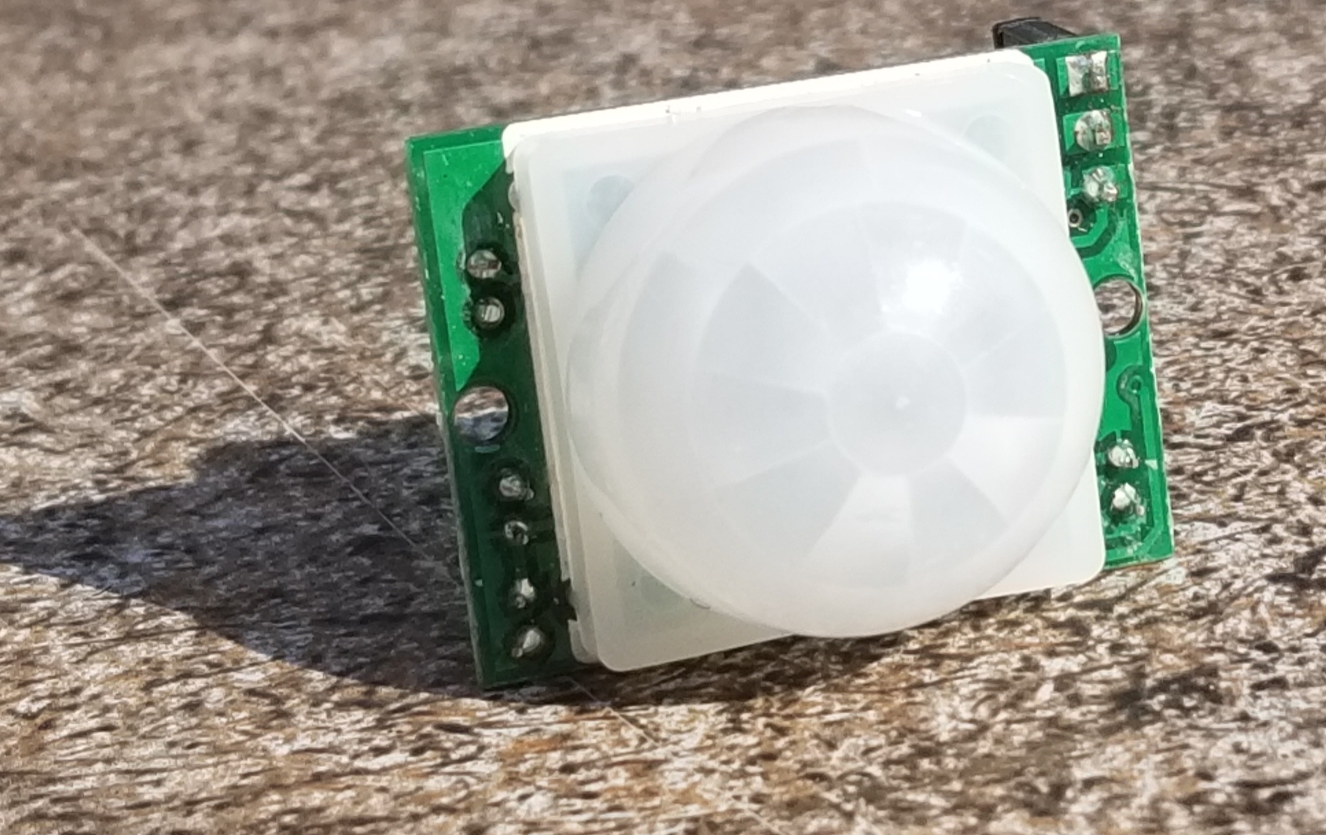
This is the passive infrared sensor that I used.
The physical build for this circuit is easy. The Passive Infrared Sensor (PIR) will get power from the VCC and ground pins of the Raspberry Pi. The signal line from the PIR can be connected to any of the GPIO pins. I’m going to use pin 3. The circuit will need to be put in an enclosure to protect it from rain or humidity in general. If your enclosure doesn’t already have a weather protected way to get power in your options are to either run the Pi off of a battery that is within the enclosure (that means periodic recharging) or drill a hole for the wires yourself and apply a sealant.
There are a lot of languages that I could use for writing my program on the Pi. Python, Java, and C/C++ make the top of the list (in no specific order). For this project I’ve decided to go with Java. To interact with the pins in Java we will need to import classes from com.pi4j.io and com.pi4j.wiringpi. These are not standard libraries; they exists to provide an interface to the pins. To demonstrate reading a pin in Java here is a simple program that will print text in a look that reflects the pin state.
import com.pi4j.io.*;
import com.pi4j.wiringpi.Gpio;
import com.pi4j.wiringpi.GpioUtil;

public class PinTest {
   public static void main(String args[]) throws InterruptedException {
      final GpioController gpio = GpioFactory.getInstance();
      Gpio.pinMode (3, Gpio.INPUT) ;
      while(true) {
         if (Gpio.digitalRead(3) == 0){
               System.out.println(The Pin is ON");
         }else{
            System.out.println("The Pin is OFF");
         }
      }
   }
}
Phillips has an SDK for Java. You might see it present as an SDK for Android, but it works fine in other Java environments. A convenience from this is that a significant portion of the development can be done on your computer of choice. I did most of the development on a Mac and used git to transfer it to the Raspberry Pi when done.

The color Hue lighting can take on a variety of colors.
The overall execution loop of the program will check whether or not the trigger condition has occurred. If the trigger condition has occurred then the program will activate a scene. If not then it deactivates the scene. The program loop also contains some debouncing logic. Depending on the type of sensor used and the sensors characteristics a sensor could change states with ever cycle. I’ve chosen to only deactivate if a certain amount of time has passed since the last activation. For initial development instead of interfacing to an actual sensor I have a method that is returning a random Boolean value. When the code is moved to the Raspberry Pi this method will be updated to read the state of the actual sensor. The following will only deactivate after there have been 2 seconds with no activation event.
    boolean getActivationState() {
        return random.nextBoolean();
    }

    void runLoop() throws InterruptedException{
        System.out.println("running");
        long lastActivation = System.currentTimeMillis();
        while(true) {
            Thread.sleep(100);
            boolean isActivated = getActivationState();
            if(isActivated) {
                lastActivation = System.currentTimeMillis();
                activateScene();
            }
            else {
                long now = System.currentTimeMillis();
                if ((now - lastActivation)> 2000)
                    deactivateScene();
            }
        }
    }
Controlling the lights happens through the Hue SDK. Before activating the lights the Hue bridge must be discovered. While Hue makes a series of lights that have Bluetooth controllers built in and can be controlled without the Hue Bridge currently they only support APIs through the bridge. It is a required hardware component.
The SDK already contains functions for discovering the bridge. All that a developer needs to do is initiate a search and implement a callback object that will receive information on the bridges discovered. In the following I instantiate the Phillips Hue SDK object and register a listener. If the program had been connected with a bridge before the IP address if that bridge is loaded and it reconnects to it. Otherwise the search is initiated. As the search occurs the earlier registered listener receives callbacks.
private void init() {
    this.loadSettings();
    System.out.println("Getting SDK instance");
    phHueSDK = PHHueSDK.create();
    System.out.println("Setting App Name");
    phHueSDK.setAppName("HolidayLights");
    phHueSDK.setDeviceName("RaspPi");
    System.out.println("SDK initialized");
    phHueSDK.getNotificationManager().registerSDKListener(listener);

    if(this.getLastIpAddress()  != null) {
        System.out.println("Connect to last access point");
        PHAccessPoint lastAccessPoint = new PHAccessPoint();
        lastAccessPoint.setIpAddress(getLastIpAddress());
        lastAccessPoint.setUsername(getUserName());
        if (!phHueSDK.isAccessPointConnected(lastAccessPoint)) {
            phHueSDK.connect(lastAccessPoint);
        }
    } else {
        System.out.println("Searching for access point");
        PHBridgeSearchManager sm = (PHBridgeSearchManager) phHueSDK.getSDKService(PHHueSDK.SEARCH_BRIDGE);
        // Start the UPNP Searching of local bridges.
        sm.search(true, true);
    }
}
The listener is of type PHSDKListener. I won’t show the full implementation here but will show some of the more relevant parts.
When the bridges are found they are returned as a list. I’ve only got one on my home network and so I connect to the first one seen. If you have more than one bridge you’ll need to implement your own logic for making a selection.
@Override
public void onAccessPointsFound(List accessPoint) {
    System.out.println("Access point found");
    if (accessPoint != null && accessPoint.size() > 0) {
        System.out.println("Number of access points: "+new Integer(accessPoint.size()).toString());
        phHueSDK.getAccessPointsFound().clear();
        phHueSDK.getAccessPointsFound().addAll(accessPoint);
        phHueSDK.connect(accessPoint.get(0));
    }
}
When the connect attempt is made it is necessary to press the pairing button on the bridge. The console will print a message from the SDK saying this. Once the bridge is connected I save an instance of the bridge and the a
        @Override
        public void onBridgeConnected(PHBridge b, String username) {
            HolidayController.this.bridge = b;
            isBridgeConnected = true;
            System.out.println("on bridge connected...");
            phHueSDK.setSelectedBridge(b);
            phHueSDK.enableHeartbeat(b, PHHueSDK.HB_INTERVAL);
            phHueSDK.getLastHeartbeat().put(b.getResourceCache().getBridgeConfiguration() .getIpAddress(), System.currentTimeMillis());
            setLastIpAddress(b.getResourceCache().getBridgeConfiguration().getIpAddress());
            setUserName(username);
        }
After the bridge connects the SDK will query the state of the lights on the system and update some objects representing the last known state of each light. The first time the cache is updated the program prints the name of each light and the light’s identity. This information is useful for selecting which lights will be controlled. The light list is saved for the program to use.
        @Override
        public void onCacheUpdated(List<Integer> arg0, PHBridge bridge) {
            if(!isDeviceListPrinted) {
                PHBridgeResourcesCache rc = bridge.getResourceCache();
                List<PHLight> lightList = rc.getAllLights();
                HolidayController.this.lightList = lightList;
                ListIterator<PHLight> it = lightList.listIterator();
                while(it.hasNext()) {
                    PHLight l = it.next();
                    System.out.println(l.getIdentifier() + "    " + l.getName());
                }
                isDeviceListPrinted = true;
            }
        }
With that in place we now have enough information to change the state of the lights. To test things out I started with implementations of activateScene and deactivateScene that will just turn all the Hue lights on and off (don’t do this if you have other people in your dwelling that this would affect).
void activateScene() {
    ListIterator<PHLight> it = lightList.listIterator();
    while(it.hasNext()) {
        PHLight l = it.next();
        System.out.println(l.getIdentifier() + "    " + l.getName());
        PHLightState state = l.getLastKnownLightState();
        state.setOn(true);
        state.setBrightness(254);
        float[] xy = PHUtilities.calculateXYFromRGB(
            0xFF & ((int)color>> 0x10),
            0xFF & ((int)color >> (long)0x08),
            0xFF & (int)color, l.getModelNumber());
        l.setLastKnownLightState(state);

        bridge.updateLightState(l.getIdentifier(), state,  NOPListener);
    }
    isDeviceListPrinted = true;
}

void deactivateScene() {
    ListIterator<PHLight> it = lightList.listIterator();
    while(it.hasNext()) {
        PHLight l = it.next();
        System.out.println(l.getIdentifier() + "    " + l.getName());
        PHLightState state = l.getLastKnownLightState();
        state.setOn(false);
        //state.setBrightness(254);
        l.setLastKnownLightState(state);

        this.bridge.updateLightState(l.getIdentifier(), state,  NOPListener);
    }
    isDeviceListPrinted = true;
}
If the program is run at this point the lights will turn on and off somewhat randomly. Ultimately we don’t want it to control all the lights. Instead I want to be able to specify the lights that it is going to control. I’ve made a JSON file file that contains a couple of elements. One is the RGB color that I want to use in the form of an integer, the other is an array of numbers where each number is an ID for the light to be controlled. The RGB color is specified here as a base 10 number instead of the normal base 16 that you may see used for RGB codes. Unfortunately JSON doesn’t support hexadecimal numbers 🙁.
{
    "lights":[5, 7, 9],
    "color": 16711935
}
These values are read by the code. Before the code acts on any light it checks to see if its identifier is in this array before continuing. During activation if the identifier is in the array the light’s state is set to on, brightness is set to full, and the color is applied. The color must be converted to the right color space before being applied to the light; something that is done with a utility function that the SDK provides.
void activateScene() {
    System.out.println("activating scene");
    ListIterator<PHLight> it = lightList.listIterator();
    while(it.hasNext()) {
        PHLight l = it.next();
        if(isTargetLight(l.getIdentifier())) {
            System.out.println(l.getIdentifier() + "    " + l.getName());
            PHLightState state = l.getLastKnownLightState();
            state.setOn(true);
            state.setBrightness(254);
            float[] xy = PHUtilities.calculateXYFromRGB(
                0xFF & ((int)color>> 0x10),
                0xFF & ((int)color >> (long)0x08),
                0xFF & (int)color, l.getModelNumber()
            );
            state.setX(xy[0]);
            state.setY(xy[1]);
            l.setLastKnownLightState(state);
            bridge.updateLightState(l.getIdentifier(), state,  NOPListener);
        }
    }
}

void deactivateScene() {
    System.out.println("deactivating");
    ListIterator<PHLight> it = lightList.listIterator();
    while(it.hasNext()) {
        PHLight l = it.next();
        if(isTargetLight(l.getIdentifier())) {
        System.out.println(l.getIdentifier() + "    " + l.getName());
        PHLightState state = l.getLastKnownLightState();
        state.setOn(false);
        l.setLastKnownLightState(state);

        this.bridge.updateLightState(l.getIdentifier(), state,  NOPListener);
        }
    }
}
The last steps needed to make the device work as intended are to update the getActivationState() function to read the actual state of the motion sensor instead of a random value and wiring the motion sensor to a Raspberry Pi. From hereon the code is only going to work on a Raspberry Pi since the libraries for reading the pins are only applicable to this device. It is possible to dynamically load class libraries and use them as needed for the specific platform on which code is running. But information on doing that is beyond the scope of what I wish to discuss here.
I’m declaring a GpioController variable at the class level and am instantiating it in the constructor. I also set the mode of the IO pin that I’ll be using to input.
    GpioController gpio;

    HolidayController() {
        gpio = GpioFactory.getInstance();
        Gpio.pinMode (3, Gpio.INPUT) ;
        //....
     }
The getActivationState() implementation only needs to contain a single line.
boolean getActivationState() {
   return Gpio.digitalRead(3);
}
With that change it will now work. If the Raspberry Pi is placed in a position where the motion sensor has a view of the space of interest then it will control the lights. If you are using one of the earlier Raspberry Pis (anything before the Raspberry Pi 4) you should be able to also power the Pi off of a portable phone charger; there are many that will make sufficient batteries for the Pi. The Raspberry Pi 4 has higher energy requirements and you may run into more challenges finding a portable power supply that works.
Why use the Pi at all for this? Because there is a lot of room to expand. Such as using the video capabilities of the pi to power a display or controlling other devices. Controlling the lights is a start. I’ll be revisiting this project for add-ons in the future.
If you want to start on something similar yourself the following (affiliate) links will take you to the products on Amazon.
Parts Lists