Samsung HOLOLAB

1T3A0114.JPG

One of the technology implementations displayed at SDC 2018 was their HOLOLAB. Curious as to what it is I walked over. It was a rig for performing 3D scanning of subjects. A few of the tangible outcomes included some pretty elastic 3D printed statues of people, a volume metric display showing a subject, and a display showing one of the scanned subjects dancing.

I was more curious about the implementation. I got a picture peering into the space to see how the physical structure was built. Inside the space the ambient lighting was ramped up by way of LEDs distributed around the space and 52 Point Grey Research cameras, all mounted to various places on an 8020 rig.

The software is custom built. I asked of its commercial availability and the Samsung rep I spoke to told me, “it was a work in progress.” The rep indicated that they are planning to have some popup locations available in the future for more people to try it and receive a copy of their models.

It is still early in the conference, but I might take a moment to try it out myself.

1T3A0122.JPG
Inside the HoloLab

1T3A0115.JPG


Tizen 5.0 Released

Tizen-Pinwheel-On-Light-RGB

Tizen 5.0 was released a few days ago. This is a week in advance of the Samsung Developer’s Conference 2018. For those keeping count until now the most recent version of Tizen prior to now (4.0) could be found on the Galaxy Watch and Samsung TVs. There are Mobile devices that run Tizen. But I am in the USA and those devices are not sold here (so I won’t speak on them much).

What’s new in Tizen 5.0?  There is improved IoT support, support for Bixby, and support for glTF. glTF is a format that aims to provide efficient loading of 3D scenes, but it is being added to Tizen with intent for it to be applied to watch faces.  With the upgrade we are also getting improved debugging support and a new version of Tizen.Net.  It also looks that they are deprecating the UI Builder tool in Tizen.

I get the feeling that I’ll hear more about this update when I go to the conference next week. I’ll post more from the conference as I find out 🙂

  • C# API for Display Control
  • Native API for Multi-LED control
  • Compressed File System
  • Low Memory Management
  • Upgrade to source libraries
    • icu (60.2)
    • sqlite (3.24.0)
    • json-glib (1.4.2)
    • wayland (1.15.0)
    • efl (1.21)
  • Updated Watchface Complication Framework
  • App Control API
  • Minicontrol API
  • WebView Control added
  • Network Firewall
  • Bluetooth 5.0
  • Neural Network Runtime

Samsung Developer Conference 2018 Registration Open

I previously mentioned that the dates for the Samsung Developer’s conference were announced. Registration is now open.  If you register before September 12 you can register for the lowest available price. The registration form is available over at https://www.samsungdeveloperconference.com/ . Registration is also possible on site. Currently Registration is 299 USD (+tax). After the 12th it will go up to 399 USD. On site registration is 499 USD.

Registration for the Samsung Developer's Conference, 2018

Obtaining the Connection String for a Provisioned Windows IOT Device

Playing with the code that I was using to get data from my car and stream it to the cloud I did something that I knew was a no-no; I hard coded the connection string in the code. There’s a number of reasons to not do this*; it’s less secure as someone can potentially extract the connection string and use it for unauthorized access and if the connection string ever needs to change then code needs to be recompiled and redeployed.

When a Windows IOT device is provisioned there is a connection string that is managed by the device; your application can take advantage of this and need not worry about the details of how it is stored. To make use of this there are a few libraries that you need to add to your UWP project. These include the followings.

  • Microsoft.Azure.Devices
  • Microsoft.Azure.Devices.Client
  • Microsoft.Devices.Tpm

With the classes in these libraries you can obtain the ID of the device and then use that ID to request an Azure DeviceClient class that is initialized with the connection string that the device is managing.

Here’s the code to do this.

DeviceClient _deviceClient;

void InitClient()
{            
    TpmDevice tpm = new TpmDevice(0);
    string hostName = tpm.GetHostName();
    string deviceId = tpm.GetDeviceId();
    string sasToken = tpm.GetSASToken();            
    var client = DeviceClient.Create(
        hostName, 
        AuthenticationMethodFactory.CreateAuthenticationWithToken(deviceId, sasToken),
        TransportType.Mqtt
    );
}

Connecting to Bluetooth RFCOMM with UWP

Soon I will be finished with a project for streaming engine data from a car and into an Azure Data Lake for analysis. I plan to post the full code for this project. But before I do I wanted to talk just about making the Bluetooth connection. The last time I wrote on this procedure it was for a Windows phone 8 project. While part of the UWP ancestry the method of connection in that project would not work in a UWP application today. Things have changed since then and the code that I used there for establishing a connection would not work today.  Treat the code used in this project as psuedo-code for now. While it was copied from a working project I’ve done some modifications to simplify it and focus on a few things here.

Getting information from the engine is easy. Every car sold in the USA (and many  parts of the world) have a diagnostic connector that can be used to query various data from the car. Getting this data is just a matter of having an interface that uses what ever protocol (there’s more than one) that your car happens to use. Don’t worry, it’s not necessary to figure this out yourself. There are products that will abstract this away and provide a common interface and protocol that can be used to communicate with all of these different protocols. One of the most popular solutions is based on a chip-set known as the ELM327. Solutions based on the ELM327 (or an ELM327 clone) will give you a serial interface through which you can send AT commands and other queries to get this information. The products that I am using use a Bluetooth interface for communicating with a computing device. You can also find implementations that use WiFi and RS232.

For development and testing there’s going to be a lot of time spent with a computer in or near a car (unless you also go out and purchase an OBD emulator). To minimize the amount of time that you have to spend around a car you may want to power one of the adapters outside of a car. I did this using a battery (sometimes a power supply) and and an OBD wire harness. Pin number 4 on the harness needs to be connected to ground and pin 16 to positive. A voltage range of 9 to 16 volts should work fine. With the device connected to power you can query information about the device itself but nothing about the car.  While this doesn’t sound very useful at first it’s enough to get the basic Bluetooth connectivity code working.

OBDSetup

For development hardware I am using a Dragonboard 410x running Windows IOT. The UWP based solution, while targeting Windows IOT, runs just fine from a PC. I believe it will run fine from a Raspberry Pi 3 also. Just for fun I tried an old Windows 10 device that I still have in the house and the code ran without any modifications needed from there. So grab what ever Windows 10 device that you have and try it out!

For the application to be able to connect to the device over Bluetooth there are some capabilities that must be declared in the UWP application. I don’t suggest using the Visual Studio for doing this. It doesn’t expose all of the necessary capability settings that are needed. It’s easier to do this in the text editor.

Right-clicking on the project’s manifest gives the option to open it in the code editor. Scrolling down to the Capabilities section I added the following. Some of these properties are needed to access the Bluetooth serial port. Some others are there because they are parts of the project that I will talk about in future post.

  
  <Capabilities>
    <apability Name="internetClient" />
    <DeviceCapability Name="bluetooth" />
    <DeviceCapability Name="proximity" />
    <DeviceCapability Name="location" />
    <DeviceCapability Name="bluetooth.rfcomm">
      <Device Id="any">
        <Function Type="name:serialPort" />
      </Device>
    </DeviceCapability>
  </Capabilities>

I had already paired the Bluetooth device with my Windows IOT device. While the devices are paired with each other the application doesn’t know about the pairing. It still needs to discover the device. To do this I use a device watcher to scan for devices. I know the one that I want to find is named “OBD”. I’ve hard coded this into my solution. The end solution that I’m making doesn’t have a UI, If it did then I would have also made use of the UI that allows a user to select a device being paired.

DataReader _receiver;
DataWriter _transmitter;
StreamSocket _stream;
DeviceWatcher _deviceWatcher;

string[] requestedProperties = new string[] { "System.Devices.Aep.DeviceAddress", "System.Devices.Aep.IsConnected" };
_deviceWatcher = DeviceInformation.CreateWatcher("(System.Devices.Aep.ProtocolId:=\"{e0cbf06c-cd8b-4647-bb8a-263b43f0f974}\")",
                                               requestedProperties,
                                               DeviceInformationKind.AssociationEndpoint);
_deviceWatcher.Stopped += (sender,x)=> {
    _isScanning = false;
    Log("Device Scan Halted");
};
EngineDataList.Add("started");
_deviceWatcher.Added += async (sender, devInfo) =>
{
    Log($"Found device {devInfo.Name}");
    System.Diagnostics.Debug.WriteLine(devInfo.Name + "|" + devInfo.Kind + "|" + devInfo.Pairing);
    if (devInfo.Name.Equals("OBDII"))
    {
     // More Code Goes Here
     //Lets talk about that in a sec
    }
};

_deviceWatcher.Start()

The above code will give result in the DeviceInfo object for the Bluetooth adapter being returned. Now we can connect to it and open up streams for reading and writing. The code for creating these streams would be where I have the comment placed in the above. The following is the code that would go in that place.

try
{
    DeviceAccessStatus accessStatus = DeviceAccessInformation.CreateFromId(devInfo.Id).CurrentStatus;
    if (accessStatus == DeviceAccessStatus.DeniedByUser)
    {
        Debug.WriteLine("This app does not have access to connect to the remote device (please grant access in Settings > Privacy > Other Devices");
        return;
    }
    var device = await BluetoothDevice.FromIdAsync(devInfo.Id);
    Debug.WriteLine(device.ClassOfDevice);

    var services = await device.GetRfcommServicesAsync();
    if (services.Services.Count > 0)
    {
        Log("Connecting to device stream");
        var service = services.Services[0];
        _stream = new StreamSocket();
        await _stream.ConnectAsync(service.ConnectionHostName,
        service.ConnectionServiceName);
        _receiver = new DataReader(_stream.InputStream);
        _transmitter = new DataWriter(_stream.OutputStream);
        
        ReceiveLoop();
        QueryLoop();
        _deviceWatcher.Stop();
    }
}catch(Exception exc)
{
    Log(exc.Message);
}
catch
{
    Log("Native Error");
}

After this runs the devices are connected to each other. The devices would interact by the Win IOT device sending a query and getting a response. For now the only query that will be sent is the string “AT\n”. On devices that accept AT command sets the command AT should only result in the response OK. This is useful for testing the connection without actually having the device perform an operation that would change the state of the system being used.

void QueryLoop()
{
    Task t = Task.Run(async () =>
    {
        
        while (true)
        {
            _transmitter.WriteString(msg);
            _transmitter.WriteString("\r");
            await _transmitter.StoreAsync();
            await Task.Delay(50);
        }
    }
    );
}

void ReceiveLoop()
{
    Task t = Task.Run(async () => {
        while (true)
        {
            uint buf;
            buf = await _receiver.LoadAsync(1);
            if (_receiver.UnconsumedBufferLength > 0)
            {
                string s = _receiver.ReadString(1);
                receiveBuffer.Append(s);
                if (s.Equals("\n")||s.Equals("\r"))
                {
                    try
                    {
                      Debug.WriteLine("Message Received:"+receiveBuffer.ToString());
                        receiveBuffer.Clear();
                    }
                    catch(Exception exc)
                    {
                        Log(exc.Message);
                     
                    }
                }
            }else
            {
                await Task.Delay(TimeSpan.FromSeconds(0));
            }
        }
    });
}

When the above runs the debug output stream will print a series of OK responses. To do something more useful with it we need to know what commands to send to it and how to parse the responses. If you send the command 01 0C while the adapter is connected to a car you will get back a hex response that starts with 41 0C followed by some additional hex numbers. The additional hex numbers are the RPMs of the car. That’s one of the metrics I started off querying because it’s something that I can change without driving the car; for this I can pull the car out of the garage, put it in the driveway, and rev the engine without worrying about carbon monoxide poisoning. I’ll talk about how to find out what metrics that you can query in your car in my next post on this project.

ELM327 Bluetooth Adapter on Amazon

Simplified UWP View Mode Base

If you’ve implemented a ViewModelBase (or some object that implements INotifyPropertyChanged) in UWP there’s a pattern that you will recognize. When a property value is being set you might check to see if the new value is different from the previous value, if it is then you assign the value to the property and call the OnPropertyChanged event. Such code might look something like this.

public abstract class ViewModelBase: INotifyPropertyChanged {
   public event PropertyChangedEventHandler PropertyChanged;
   protected OnPropertyChanged(String propertyName)
   {
      PropertyChanged(this, new PropertyChangedEventArgs(propertyName));
   }
}

public class Employee : ViewModelBase{
   private int _employeeID; 
   public int EmployeeID
   {
      get { return _employeeID; }
      set 
      {
         if(_employeeID != value )
         {
            _employeeID = value;
            OnPropertyChanged("EmployeeID")
         }
      }
   }
}

While it works it could be better. The first improvement is in the implementation of OnPropertyChanged. If someone my a typo in the name of the property it might not noticed until runtime debugging (if at all). It would be better if such an error were caught at compile time. There’s a different implementation of OnPropertyChanged that can do this.

protected void OnPropertyChanged(Expression expression)
{
   OnPropertyChanged(((MemberExpression)expression.Body).Member.Name);        
}

With this implementation instead of typing the name of the property we can type an expression for the property. If we make a mistake in the expression it will cause a compile time error. Out Employee class will now look like the following.

public class Employee : ViewModelBase{
   private int _employeeID; 
   public int EmployeeID
   {
      get { return _employeeID; }
      set 
      {
         if(_employeeID != value )
         {
            _employeeID = value;
            OnPropertyChanged(()=>EmployeeID)
         }
      }
   }
}

That’s improved, but there’s still room for improvement. Checking for the value to be different and then conditionally assigning the value can be modularlized so that we don’t have to keep typing it. To do this I add a couple of additional methods to the ViewModelBase.

protected bool SetValueIfChanged(Expression<Func> propertyExpression, Expression<Func> fieldExpression, object value)
{
    var property = (PropertyInfo)((MemberExpression)propertyExpression.Body).Member;
    var field = (FieldInfo)((MemberExpression)fieldExpression.Body).Member;
    return SetValueIfChanged(property,field, value);
}

protected bool SetValueIfChanged(PropertyInfo pi,FieldInfo fi, object value)
{
    var currentValue = pi.GetValue(this);
    if ((currentValue == null && value == null)||(currentValue!=null &&  currentValue.Equals(value)))
        return false;
    fi.SetValue(this, value);
    OnPropertyChanged(pi.Name);
    return true;
}

The second version of this method is probably easier to understand. It uses classes from the reflection namespace to interact with the object. This allows it to operate on on any properties or fields as long as the reflection data is passed. The first implementation of this method takes an expression and gets the reflection data from it. Applying this to the Employee class it now looks like the following.

public class Employee : ViewModelBase{
   private int _employeeID; 
   public int EmployeeID
   {
      get { return _employeeID; }
      set { SetValueIfChanged(()=>EmployeeID, ()=>_employeeID, value); }
   }
}

Much better. Now if I want to reduce my typing even more instead of naming the method SetValueIfChanged I could name it something much shorter. One must still define the the fields that backup these properties. Rather than typing them out a code snippet could be defined for this pattern. A code snippet is like a template that is associated with a keystroke. I’ll talk about that in another post.

Samsung Developer Conference 2018 Dates

sdc2017logo

The dates for the 2018 Samsung Developer Conference have been announced. Outside of the dates and the location (which has been the same over the past several years) there’s not any additional information available. But if you think you might go now is the time to mark your calendars.

It’s November 7 and 8. That is a Wednesday and Thursday. As per usual it is going to be in the Moscone conference center (the West conference center).

Graphing with the HTML Canvas

Among other places I went to Peru and saw Machu Picchu! The trip back home though was long and boring.  There’s lots of ways that one can keep their mind when busy when in a non-stimulating situation though. Reading, Sudoku , cross word puzzles, so on. Sometimes I like playing with code during these times. I had started off reading a math heave book though. I generally have a notebook with me, and my notebooks are generally graph ruled. But graphing polynomials can be tedious. But hey, I had a Chromebook  with me, plenty of battery life, and no Internet access. So I decided to see what I could do with the HTML canvas. I cam up with something that worked and was useful. It’s not something that I would package and call a library by any means. After all, this is something that was put together during a layover in an airport. But nonetheless I thought it to be something that is worthy of sharing.

Drawing with the Canvas

Let’s review how to draw with the HTML5 canvas. First a <canvas> element would need to be declared within a page. Within the page’s script we grab a reference to the canvas and get the 2d context and hold onto it; the context object will be the object used for most of our interaction with the canvas. Here I take a canvas
and draw a red rectangle in it.
<canvas id="myCanvas" width="320" height="200"></canvas>

    var canvas = document.getElementById('myCanvas');
    var ctx = canvas.getContext('2d');
    ctx.fillStyle="#FF0000";
	ctx.fillRect(10,10,100,100);

Cool, we can draw on the surface. But before graphing anything we need to be able to map the data that we are graphing to the coordinate space for the graph. That’s going to be a linear transformation. Linear transformations are easy but something that I’m sure I’ll want to do several times. So I’ve made a class to figure out the the transformation for me.

Linear Transformation

Given a pair of starting and ending values this class is able to convert from on value range to another. The class has two methods. the map() method will do the conversion and rmap will perform a reverse conversion. Given the the freezing and boiling points of water in Farenheit and Celcius it could perform conversions back and forth between the two.

function linearMapping(iMin, iMax, oMin, oMax) {
	this.slope =  (oMax - oMin) / (iMax - iMin);
	this.base = oMin - this.slope*iMin;
	this.map = function(x) {
		if(typeof x != 'number')
			return null;	
		return x*this.slope+this.base;
	}
	this.rmap = function(x) {
		if(typeof x != 'number')
			return null;
		return (x - this.base)/this.slope;
	}
}

I sat for a while and I thought about the parameters that I would want to pass when creating a graph. I first envisioned passing this information as individual parameters to a function. But I didn’t have to think for long before I realized this would be a lot of parameters most of which I probably would not feel like specifying. I took a slightly different approach and decided to instead pass a parameter object. The object would be initialized with a set of workable default values that could be changed as the graph needed to be customized.

Graphing Options

Some of the basic information needed is the the size of the graph within the HTML page and the ranges of the X and Y values being displayed. I allow these values to be optionally passed in when constructing the object. I’ve also defined a color palette to be used for the graph.

function graphOptions(width, height, minX, maxX, minY, maxY) {
	this.width = width || 300;
	this.height = height || 300;
	this.minX = minX || -10;
	this.maxX = maxX ||  10;
	this.minY = minY || -10;
	this.maxY = maxY ||  10;
	this.stepX = 2;
	this.stepY = 2;
	this.backgroundColor = '#F0F0F0';
	this.lineColor = '#C0C0FF'
	this.minorLineWidth = 1;
	this.majorLineWidth = 4;
	this.dataColors = [
		"#000000",
		"#ff0000",
		"#00ff00",
		"#0000FF",
		"#FF8000",
		"#ff0080",
		"#80FF00",
		"#8000FF"
	]
}

With that we are ready to start creating our graph. We need a way of specifying where in the page the graph should be generated. I’ve made a method named makeGraph() that will accept two arguments; the parent element for the graph and the parameter object for the graph options. If for some reason the parent element isn’t specified the function will just append the graph to the page’s DOM.

Creating the Graph

This class will take care of creating the canvas object. The canvas’s context will be retained along with the options and packaged in an object as both will be needed later for plotting graphs. When the graph is created I render the graph lines on it. The canvas object is added to the page

function makeGraph(parentElement, options) {
	options = options || new graphOptions();
	var graphElement = document.createElement('canvas');

	graphElement.width = options.width;
	graphElement.height = options.height;

	var ctx = graphElement.getContext('2d');
	var newGraph = new graph(ctx, options);
	ctx.fillStyle=options.backgroundColor;
	ctx.fillRect(0,0,options.width, options.height);

	ctx.strokeStyle = options.lineColor;
	ctx.beginPath();
	ctx.lineWidth = options.majorLineWidth;
	var xOrigin = newGraph.xMapping.map(0);
	var yOrigin = newGraph.yMapping.map(0);
	ctx.moveTo(xOrigin,0);
	ctx.lineTo(xOrigin, options.height);
	ctx.moveTo(0, yOrigin);
	ctx.lineTo(options.width, yOrigin)
	ctx.stroke();
	ctx.strokeStyle = options.lineColor;
	ctx.beginPath();
	for(var i = options.minX; i<options.maxX;i+=options.stepX) {
		var xPos = newGraph.xMapping.map(i);
		ctx.moveTo(xPos,0);
		ctx.lineTo(xPos,options.height);
		ctx.lineWidth = options.minorLineWidth;
	}
	for(var i = options.minY; i<options.maxY;i+=options.stepY) {
		var yPos = newGraph.yMapping.map(i);
		ctx.moveTo(0, yPos);
		ctx.lineTo(options.width, yPos);
		ctx.lineWidth = options.minorLineWidth;
	}
	ctx.stroke();

	if(parentElement != null)
		parentElement.appendChild(graphElement)
	else
		document.body.appendChild(graphElement)
	return newGraph;
}

The result of the above is the return of a graph object that hasn’t been defined here yet. The graph object packages together the context for rendering, the graph objects, and the objects for mapping the values being represented to canvas coordinates. Something that may look odd at first is that for the Y-mapping I placed a maximum value in a minimum parameter and vice versa. This is because the coordinate system that many of us use when thinking about graphs is reversed along the Y-axis than the canvas coordinates. The general way that people think about graphs is that numbers of greater value will appear higher up on the graph. But in the canvas coordinate space the highest position has a Y-coordinate of zero and as the number increases the position maps to a position further down on a page. There’s more than one way to address this, but since the linear transfor object can already handle this if I
specify the values in a certain order that’s the solution that I used.

The function made for public use on this class ia named plot. It accepts a list of functions to be graphed. While I expect an array of functions to be passed to it if a singular function were passed that’s converted to an array of one function so that it can be treated the same way. The plot function interates through the functions passed through it passing each one to another function that does the actual work. A different color index is passed for each function.

The real work is done in plotFunction. First the X-values that fall within the range of the limits of the graph are passed to the function being mapped and the canvas-mapped result is saved to an array. The result for each X-value could either be a number or a non-number. Non-numbers will not be represented in the graph. This allows for the generation of graphs for which there may be X-values that are not part of the functions domain. If an exception occurs when calling the function being graphed the X-value association with that exception is treated as a value for which the function returns nothing. After this first pass we have an array of the canvas-mapped output values from the function.

Rendering the Graph

Next we perform the acual rendering of the output onto the graph. The function will scan ahead in the array of results to the first numerical value. This first numerical value may or may not be in the first position of the array. Once a value is found it is used as the first coordinate for a line segment. Each numerical value in the array that follows this is added to the line segment. This continues until either the end of the array is reached or a non-numerical value is encountered. In either case the accumulated points for the line segment are stroked ending. If there are more values within the array the process is repeated until the end of the array is encountered.

function graph(context, options) {
	this.ctx = context;
	this.options = options;
	this.xMapping = new linearMapping(options.minX, options.maxX, 0, options.width);
	this.yMapping = new linearMapping(options.minY, options.maxY, options.height, 0);

	this.plot = function(sourceFunctions) {
		if(!Array.isArray(sourceFunctions))
			sourceFunctions = [sourceFunctions];
		var colorNumber = 0;
		sourceFunctions.forEach((x)=> {
			this.plotFunction(x,colorNumber);
			++colorNumber;
		})
	}

	this.plotFunction = function (plotFunction, colorNumber) {
		colorNumber = colorNumber || 0;
		colorNumber = colorNumber % this.options.dataColors.length;
		var values = new Array(this.options.width);
		for(var xPos=0;xPos<this.options.width;++xPos) {
			var y = null;
			var x= this.xMapping.rmap(xPos);
			try {
				values[xPos] = this.yMapping.map(plotFunction(x))
			} catch(exc) {
				values[xPos] = null;
			}
		}
		//Find the first value that we can map
		var xPos = 0;
		while((typeof values[xPos] != 'number')&&(!Array.isArray(values[xPos]))&&(xPos < values.length))
			++xPos;
		if(xPos == values.length)
			return;
		
		while(xPos<values.length) {
			this.ctx.beginPath();
			this.ctx.strokeStyle = this.options.dataColors[colorNumber];
			this.ctx.moveTo(xPos, values[xPos]);
			while(xPos+1<values.length && typeof values[xPos+1] == 'number') {
				++xPos;
				this.ctx.lineTo(xPos, values[xPos]);
			}
			++xPos;
			this.ctx.stroke();
			while((typeof values[xPos] != 'number')&&(xPos < values.length))
				++xPos;
		}
	}
}

How Does it Look?

The graphing class is complete. Showing a graph is now only a matter of including the JavaScript in a page and using it. The simplest example of using it would be the following.

var g = makeGraph(randomPlotsArea, options);
g.plot((x)=>{return Math.sin(x); });

Here’s the result!

I’ve made a page with a few place holders for graphs. Among other things it contains the following.

<p id="randomPlots">
	
Random plots
</p> <p id="trajectoryPlotArea" >
Plot of a trajectory height for an object thrown up at 10 m/s near the earth's surface.
</p>

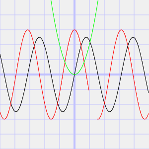
To render the graphs within their appropriate places I acquire a reference to the parent element in which the graph will be contained and I pass that to the makeGraph() function. Here I render the SIN function, the COSINE function (with no values returned from 2.0 to 3.0), and a x-squared

var randomPlotsArea = document.getElementById('randomPlots');				
var options = new graphOptions();
var g = makeGraph(randomPlotsArea, options);
g.plot([
	function(x){return 5*Math.sin(x);},
	(x)=>{
			if(Math.floor(x)!=2)
				return 6 * Math.cos(x);
			return null;
		},
	(x)=>{return x * x; }
	]);

Here is the result. The range for which no value is returned is apparent from the area in which the red line on the graph is not rendered.


Where to From Here?

Awesome! The code works! But now what?  Well, nothing for now. This was something I wrote with temporary intentions and to keep myself from being bored. That’s not to say that I’m giving up on developing a graphing library. Once back home I checked online to see what types of other graphing libraries are available. There’s a number of them, each having their own strengths. I have a direction in which I’d like to take this that is different from the others that are out there. I may revisit this, but only after a lot more thought of what I want to do, how I want this to work,  and how the variations on graphs can be specified.

Kernel Filters in HTML+JavaScript

BalloonHeader

Download Code

Kernel filters are a common approach for modifying images for various applications of image processing. They can be used to sharpen an image, blur it, or extract attributes about a picture for further processing. Implementation of the filters is simple and straight forward. I wanted to do some experiments with Kernel filters on my phone. But to my surprise the available options were not many. I decided to make my own. Before developing something for my phone I started off from a browser since my Chromebook was handy. Here I’m sharing the results.

What is a Kernel

Kernels are known by many names. Kernel, convolution matrix, and mask all refer to the same thing. Convolution is the process of adding together the values of neighboring elements of an image and applying some weight to each of the pixels. The weights, or kernel, are often expressed using matrix notation. For each one of the pixels in an image the kernel is applied to the pixel and it’s neighboring pixels to determine the new intensity for the pixel.

Manipulating Images in HTML and JavaScript

In HTML and JavaScript the image element doesn’t give direct access to its pixels for manipulation. Instead the canvas element can be used to read and write pixels. Well, not directly. With the canvas element there’s a method named getPixelData() that will return a structure that has a number array of the intensities of the pixels. After manipulation of the elements the the result can be copied back into the canvas with putPixelData().

Visually we see the pixel data as being organized in rows and columns. In memory it is organized in a single dimensional array. To read and write the correct pixel you’ll need to know how it’s organized. A single pixel is composed of 4 numbers; 3 of the numbers are for intensities of red, green, and blue and the fourth number is for transparency. These 4 elements make up a single pixel. Pixel data is usually saved continuously starting with the upper left most pixel of an image as the first one to be encoded and moving to the right from there. Once the end of a row is reached the encoding continues starting with the left most pixel on the next row.

Pretend that you had an image that was 10 pixels wide and 10 pixels tall. If you wanted to read from the pixel on the third row and fourth column (keeping in mind that zero based addressing is being used) we would need at least 20 pixels into the array to get to the third row and then another 3 more pixels to get to the fourth column. In other words we need to read the twenty third pixel. Since pixels are composed of four elements this works out to the reading starting with index 92 of the array to get the red portion of the pixel and indices 93, 94, and 95 to read the green, blue, and transparency portions. Given an X and Y coordinate the equation for determining what address to start reading at is as follows.

PixelIndex = (y*imageWidth+x)*4;

Since the application of the kernel can overlap with pixels that are outside the range of the image I needed to decide how to deal with attempts to read pixels that are outside of range. I could have a constant value returned (like zero for all elements), have the read address wrap around to the other side of the image, or I could cap the read coordinates. I chose to cap the read coordinates. Attempts to read a coordinate that is less than zero will result in coordinate being changed to zero. An attempt to read beyond the edge of the image results in the edge of the image being read.

I’ve covered enough theory for us to build our first kernel filter in JavaScript. Now to get to building. Kernel filters are arrays of multipliers. They can be of any dimension. The basic pieces of information that we’ll need are the dimensions of the kernel and an array holding the values for each element of the kernel. We also need to mark which position in a filter represents the center pixel.

function kernel(width, height, centerX, centerY) {
	this.width = width;
	this.height = height;
	this.centerX = centerX || Math.floor(height/2);
	this.centerY = centerY || Math.floor(width/2);
	this.weightArray = [];
	for(var h=0;h<height;++h) {
		this.weightArray.push([]);
		for(var w=0;w<width;++w) {
		 	this.weightArray[h].push(0);
		}
	}
}

Given an image we need to get the image data from the image into the canvas. The canvas has a method named drawImage that will do this.

var width  = imageElement.naturalWidth;
var height = imageElement.naturalHeight;   
var canvas = $('')[0];
var ctx = canvas.getContext('2d');
ctx.drawImage(img,0,0);
var image = ctx.getImageData(0,0,width,height);
var pix = image.data;

To apply the filter, we will need to have a structure that contains the source data and another for writing the results. The results cannot be written to the same structure that we are reading from as this would overwrite some of the pixels that still need to be read for other processing.

var getPix = function(x,y) {
      x = Math.max(0, Math.min(x, width -1));
      y = Math.max(0, Math.min(y, height-1));
      var address = (y*width+x)*4;
      return [pix[address+0], pix[address+1], pix[address+2], pix[address+3]];
    }
    
    var getFilteredPix = function(x,y, kernelFilter) {
      var retVal = [0,0,0,0];
      for(var fy=0;fy<kernelFilter.height;++fy) {
        for(var fx=0;fx<kernelFilter.width;++fx) {
          var m = kernelFilter.weights[fy][fx];
          var pix = getPix(x+fx-kernelFilter.centerX, y+fy+-kernelFilter.centerY);
          retVal[0]+=pix[0]*m;
          retVal[1]+=pix[1]*m;
          retVal[2]+=pix[2]*m;
          retVal[3]+=pix[3];
        }
      }
      return retVal;
    }
    
    for(var yp=0;yp<height;++yp) {
      for(var xp=0;xp<width;++xp) {
        var newVal = getFilteredPix(xp,yp);
        var address = (yp*width+xp)*4;
        resultPixelData[address+0] = newVal[0];
        resultPixelData[address+1] = newVal[1];
        resultPixelData[address+2] = newVal[2];
        resultPixelData[address+3] = newVal[3]
      }
    }

With that in place we can now view the results of various kernel filters. Using the same source image here are a few filters and the result of them being applied. This is the original image that I’ll be working with.

balloon

Identity

0 0 0
0 1 0
0 0 0

As suggested by the name the identity filter does not result in any change on
the image, much like other identity operations in math like adding 0 to a number
or multiplying and dividing by 1.

balloon

Edge Detection

-1 -1 -1
-1 8 -1
-1 -1 -1

The edge detection filter highlights high contrast areas of an image resulting in lines
showing where these areas meet. If you wanted to produce an outline of a subject this
would be one of your go-to filters.
balloonEdge


Emboss

-2 -1 0
-1 1 1
0 1 2

The Embose filter produces an image with a 3d effect making it look like the image has been pressed into a material. Various areas of the image will appear to be raised or depressed.

balloonEmbose

Box Blur

0.111 0.111 0.111
0.111 0.111 0.111
0.111 0.111 0.111

The Box Blur simply averages the pixels in an area together. Here I show a 3×3 filter. For the image shown here I actually used a 10×10 filter for the sake of exagerating the effect to make it more visible here.

balloonBlur

This gives me something quick I can use for testing out image filters. It could be better though. Right now, to apply a different filter I need to modify code. Wouldn’t it be nice if the filter data were externalized allowing for filters to be saved and shared? I’ll look at that the next time I revisit this project.

GTX 1050, WDDM 2.2, and Windows Mixed Reality

Update

It took a lot more digging, but I did find the source of this problem. While the video card *did* match requirements the problem was the processor generation. Since it was below the required generation there were some features that were not enabled in the video card drivers. Since some features were not enabled in the video card drivers the video card itself appeared to not meet requirements.

Original

I’ve got some Windows Mixed Reality Immersive headsets in hand. The experience is pretty cool. But I wanted to figure out what the minimum requirements are to use them so that we could get new hardware for some of the other developers. Microsoft has minimum requirements listed on a page. Not being one to take such a thing on word value (especially not for a new product) I decided to validate these requirements. The item I was questioning was the video card. The requirements list the NVidia GTX 1050 as the minimum video card. I made my way over to my local Best Buys and picked one up.

It was installed into a Machine that already had the Windows 10 Creator’s Update on it. When I started the Mixed Reality application I got the following.

CantRunMixedRality

I tried several driver versions from the ones released in April (version 381.65, which were the first to have VR support) to the most recent at the time of this writing (385.28).

Digging a little deeper I received a rather cryptic message from the NVidia GeForce software on Virtual Reality support. The software told me that this video card didn’t meet requirements for Virtual Reality. I needed to have at least an NVidia GTX 1050, and the card in the machine was only a NVidia GTX 1050. That’s not a typo, it showed the same card for both the required minimum and what was installed. I get the impression that there was the intention to support VR in this card but it just never happened.

As of yet the consumer release of the Mixed Reality features has not occurred. We are still in a time frame in which things could change rapidly. This card might be supported by then. From some exchanges with others though of you are looking to get a card that supports the Windows Mixed Reality headsets start of with NVidia’s GTX 1060 as a minimum.


Using PowerShell to Setup SpectatorView

SpectatorViewSetup

I have some down time and spent some of the time to clear the drive on a computer, reinstall Windows, and rebuild my development environment. While I was doing this I decided to try out SpectatorView for the HoloLens. For those unfamiliar SpectatorView is a solution for creating recordings of what one sees through a HoloLens. The HoloLens does have a recording feature built in, but that feature is low resolution. Using SpectatorView one can produce a high resolution recording. Using a high resolution camera mounted to a HoloLens and a video capture a computer takes the motion data stream from the HoloLens to overlay objects from a HoloLens program onto a video stream. I tried it out last week with a 1K camera (Canon 5D Mark III) and it works great!

One of the personal goals that I have is that when possible to automate setup steps for a development environment, especially if I may need to do them again. I expect to see a fast return on investment for doing this either through time saved when I seed to setup an environment for myself again or when coworkers are able to save time by being able to use the scripts that I’ve made. Up until now my use of PowerShell has been light, but it looked to be the perfect scripting language for this task. For the most part PowerShell gives access to the COM, WMI, and .Net objects in a scripted environment.

Software and Files Needed for Spectator View

To setup SpectatorView there are a number of software components that are needed.

    • Visual Studio
    • Unity
    • BlackMagic DeckLink SDK
    • Hololens Companion Toolkit
    • Hololens Toolkit
    • OpenCV 3.2
    • Canon SDK (Optional)

Unity and Visual Studio are frequently used within my team, so I’m starting off with the assumption that these two components are already present. Getting the other components is easy enough, so I don’t expect an attempt at scripting the acquisition and installations for it to save much time. But I also feel that initial attempts at scripting are better applied to something simple to allow for problems to be found before being applied to more complex scenarios. The Canon SDK can only be downloaded if someone registers with Canon, requests access to the SDK, and then downloads the SDK after receiving approval to download the SDK. Since there are manual steps involved in getting access to the Canon SDK I did not script the acquisition of the file. Similarly the BlackMagic Decklink SDK also requires registration to download. While I could not script the acquisition of these two files I was still able to handle them post download in my script. Each version of these SDKs have a slightly different name since the version number is a part of the file name. To keep the script easy to use it will figure out the actual name of the file when run. If a new version of one of the SDKs were to be used it would only be necessary to replace the ZIP file being used.

Cloning the HoloLend Companion Kit with github

The Hololens Companion Kit is the easiest of the components to acquire through a script. It can be downloaded using GIT. So I won’t spend much time talking about how to download it and only mention it at all since it is a necessary component.

$openCVUrl = "https://downloads.sourceforge.net/project/opencvlibrary/opencv-win/3.2.0/opencv-3.2.0-vc14.exe?r=http%3A%2F%2Fopencv.org%2Freleases.html&ts=1501614414&use_mirror=iweb";
$companionKitFilePath = $PSScriptRoot + "\HoloLensCompanionKit";
$kitIsDownloaded = Test-Path $companionKitFilePath;
if(!$kitIsDownloaded) {
	git clone $hololensCompanionKitURL;
}

If you are not familiar with what the Test-Path command means don’t worry about it just yet. I’ll explain it’s use when it is used on another component.

File Paths

Leaving nothing to be ambiguous many of the file locations referenced are relative to the location of the power script file. In PowerScript There is a variable named $PSScriptRoot whose value is the full path to the folder from which the script is run. While not absolutely necessary I build paths to various files and folders using this variable.

Downloading OpenCV

For downloading the OpenCV source I’ve placed the URLs for OpenCV from one of the mirrors in a variable at the top of my script. If I ever wanted to change the version of OpenCV used I would need to change the value in this variable. There are several ways to download a file in PowerScript. I decided to use .Net’s WebClient because of speed and predictability. I considered using BITS but when using BITS to download you can’t know when the service will get around to downloading the file; it will do so on it’s own schedule. Downloading the file with the WebClient is easy. But it provides no feedback while it works. Just so that someone using the script doesn’t think that something is wrong I decided to print a message letting them know to hold on for a moment.

$openCVUrl = "https://downloads.sourceforge.net/project/opencvlibrary/opencv-win/3.2.0/opencv-3.2.0-vc14.exe?r=http%3A%2F%2Fopencv.org%2Freleases.html&ts=1501614414&use_mirror=iweb";			
$webClient = New-Object System.Net.WebClient;
$openCVArchivePath = $openCVFolder + "\archive.exe"
Write-Host "Downloading OpenCV. This is going to take a while..." -foreground "Green"
$webClient.DownloadFile($openCVUrl,$openCVArchivePath );

If you were to take the above and put it in a file with a “ps1” extension and run it you’ll find that a file downloads named archive.exe. OpenCV for Windows is distributed in a self extracting archive (Which is why it uses an EXE extension instead of ZIP). Once the files is downloaded if you were to run it you would be greeted with a prompt asking where you want the file to be extracted. For automating the setup I don’t want the archive to give these prompts. I’ll invoke it passing to it on the command line the location that it should use. Adding those arguments to the above script we end up with the following.

$openCVUrl = "https://downloads.sourceforge.net/project/opencvlibrary/opencv-win/3.2.0/opencv-3.2.0-vc14.exe?r=http%3A%2F%2Fopencv.org%2Freleases.html&ts=1501614414&use_mirror=iweb";			
$webClient = New-Object System.Net.WebClient;
$openCVFolder = "${PSScriptRoot}\openCV\openCV3.2"
$openCVArchivePath = $openCVFolder + "\archive.exe"
Write-Host "Downloading OpenCV. This is going to take a while..." -foreground "Green"
$webClient.DownloadFile($openCVUrl,$openCVArchivePath );
Write-Host "Download complete";
& "${openCVArchivePath}" -o "${openCVFolder}" -y

This works. But i wanted it to be possible to run this script more than once if it failed for some reason. To prevent the script from reinstalling OpenCV again if it had been installed before I check for the existence of the OpenCV folder. This is a less than thorough test as it would not detect conditions such as an archive being partially unzipped before failing. But this is satisficing for my purposes. The Test-Path< command can be used to determine whether or not a file object exists at some path. I wrapped the above code in a block that checks for the existence of the OpenCV folder first.

$openCVIsDownloaded = Test-Path $openCVFolder
if(!$openCVIsDownloaded) {
	## Download code goes here
}

Unpacking the Canon and BlackMagic SDKS

The BlackMagic and Canon SDKs are both in ZIP files. Unpacking them will be about the same. I’ll only talk about the Canon SDK for a moment. But the there’s equal applicability to what I am about to say to both. Like the OpenCV SDK I’ll check to see if the folder for the Canon SDK exists before trying to unpack it. The script requires that the Canon SDK zip file be in the same folder as the script. The Canon SDK versions all start with the same prefix. They all start with EDSDK. To find the file I use the Get-ChildItem command to get a list of files. If there is more than one version fo teh SDK in the folder sorting the results and taking the last should result in the most recent one being selected. PowerShell allows the use of negative index numbers to address an item from the end of a list. Index -1 will be the last item in the list. Taking the last item and getting its FullName value will give the path to the zip file to be unzipped. The Expand-Archive command will unzip the file to a specified path.

################################################
# Unpacking the Canon SDK
################################################
$CanonSDKIsPresent = Test-Path "${PSScriptRoot}\CanonSDK";
if(!$CanonSDKIsPresent)
{
	#Find the Canon SDK Zip(s) present
	$canonSdkArchiveList = Get-ChildItem "${PSScriptRoot}\EDSDK*.zip" | Sort;
	$canonSDKZip = $canonSdkArchiveList[-1].FullName
	Expand-Archive  -path $canonSDKZip -DestinationPath "${PSScriptRoot}\CanonSDK";
} 
################################################
# Unpacking the Black Magic SDK
################################################
$BlackMagicSDKIsPresent = Test-Path "${PSScriptRoot}\BlackMagicSDK";
if(!$BlackMagicSDKIsPresent) 
{
	#Find the Black Magic SDKs present
	$blackMagicSDKList = Get-ChildItem "${PSScriptRoot}\Blackmagic_Decklink_SDK*.zip";
	$blackMagicZip = $blackMagicSDKList[-1].FullName;
	Expand-Archive  -path $blackMagicZip -DestinationPath "${PSScriptRoot}\BlackMagicSDK";
}

Modifying the Visual Studio Dependencies File

The Visual Studio project that is part of the SpectatorView software requires some updates so that it knows where the various SDKs are located. The path to the BlackMagic SDK, Canon SDK, and OpenCV software must be added to it. The dependencies file dependencies.props is an XML file. The Common Language Runtime has classes for manipulating XML files. I use one of these to update this file. The exact path of each component could differ depending on which SDK version is used. Rather than hard code the path I use the Get-ChildItem command again to query for the name of folders. For the CanonSDK the line of script code to get the path looks like the following.

$canonPath = (Get-ChildItem "${PSScriptRoot}\CanonSDK")[-1].FullName+"\Windows";

There is a little more nesting that occurs with the other two SDKs. But the lines for getting their paths is similar.

$openCVPath = ((Get-ChildItem (Get-ChildItem "${PSScriptRoot}\opencv" | ?{$_.PsIsContainer} )[-1].FullName)|?{$_.PsIsContainer})[-1].FullName+"\sources\include";
$blackMagicPath = (Get-ChildItem "${PSScriptRoot}\BlackMagicSDK" | ?{$_.PsIsContainer})[-1].FullName +"\Windows";

With those paths populated I now need to load the XML file, update the values, and write them back. The Common Language Runtime’s XML class is available to PowerShell. Given a string that contains XML if that string is cast to [xml] it will be parsed and all the nodes available through its properties. To get the XML string from the contents of the dependencies files the Get-Content command will be used. Given a file path it returns the contents as a string.

$dependencies = [xml] (Get-Content -Path "${PSScriptRoot}\${HoloLensCompanionKit}\HoloLensCompanionKit\SpectatorView\dependencies.props");
$dependencies.Project.PropertyGroup[0]."OpenCV_vc14" = $openCVPath ;
$dependencies.Project.PropertyGroup[0]."DeckLink_inc" = $blackMagicPAth;
$dependencies.Project.PropertyGroup[0]."Canon_SDK" = $canonPath;
$dependencies.Save( "${PSScriptRoot}\${HoloLensCompanionKit}\HoloLensCompanionKit\SpectatorView\dependencies.props" );

Next Steps

The script is at the bottom of this post. Running this script doesn’t result in SpectatorView being 100% setup. It is still necessary to go through calibration (a step that requires you to physically do some things) in front of the camera) and copying the libraries from the sample project into your own project. There are opportunities for further automating the setup. But I felt this was a good time to write about what is working at this moment (if I wait until it is perfect ot may never get posted).

clear;
################################################
# A few download URLs
################################################
$openCVUrl = "https://downloads.sourceforge.net/project/opencvlibrary/opencv-win/3.2.0/opencv-3.2.0-vc14.exe?r=http%3A%2F%2Fopencv.org%2Freleases.html&ts=1501614414&use_mirror=iweb";
$holoLensCompanionKitURL = "https://github.com/Microsoft/HoloLensCompanionKit";
$webClient = New-Object System.Net.WebClient;
Write-Host "Running from ${PSScriptRoot}";


$companionKitFilePath = $PSScriptRoot + "\HoloLensCompanionKit";
$openCVFolder = "${PSScriptRoot}\openCV\openCV3.2"
$openCVArchivePath = $openCVFolder + "\archive.exe"

$kitIsDownloaded = Test-Path $companionKitFilePath;
if(!$kitIsDownloaded) {
	git clone $hololensCompanionKitURL;
}

$openCVIsDownloaded = Test-Path $openCVFolder
if(!$openCVIsDownloaded) {
	New-Item "$openCVFolder"  -type directory
	Write-Host "Downloading OpenCV. This is going to take a while..." -foreground "Green"
	$webClient.DownloadFile($openCVUrl,$openCVArchivePath );	
	Write-Host "Download complete";
	& "${openCVArchivePath}" -o "${openCVFolder}" -y
}
################################################
# Unpacking the Black Magic SDK
################################################
$BlackMagicSDKIsPresent = Test-Path "${PSScriptRoot}\BlackMagicSDK";
if(!$BlackMagicSDKIsPresent) 
{
	#Find the Black Magic SDKs present
	$blackMagicSDKList = Get-ChildItem "${PSScriptRoot}\Blackmagic_Decklink_SDK*.zip";
	$blackMagicZip = $blackMagicSDKList[-1].FullName;
	Expand-Archive  -path $blackMagicZip -DestinationPath "${PSScriptRoot}\BlackMagicSDK";
}
################################################
# Unpacking the Canon SDK
################################################
$CanonSDKIsPresent = Test-Path "${PSScriptRoot}\CanonSDK";
if(!$CanonSDKIsPresent)
{
	#Find the Canon SDK Zip(s) present
	$canonSdkArchiveList = Get-ChildItem "${PSScriptRoot}\EDSDK*.zip" | Sort;
	$canonSDKZip = $canonSdkArchiveList[-1].FullName;
	Expand-Archive  -path $canonSDKZip -DestinationPath "${PSScriptRoot}\CanonSDK";
} 
else 
{
	Write-Host "Canon SDK already present";
}
################################################
# Modifying the Dependencies File
################################################
$canonPath = (Get-ChildItem "${PSScriptRoot}\CanonSDK")[-1].FullName+"\Windows";
$openCVPath = ((Get-ChildItem (Get-ChildItem "${PSScriptRoot}\opencv" | ?{$_.PsIsContainer} )[-1].FullName)|?{$_.PsIsContainer})[-1].FullName+"\sources\include";
$blackMagicPath = (Get-ChildItem "${PSScriptRoot}\BlackMagicSDK" | ?{$_.PsIsContainer})[-1].FullName +"\Windows";

$dependencies = [xml] (Get-Content -Path "${PSScriptRoot}\${HoloLensCompanionKit}\HoloLensCompanionKit\SpectatorView\dependencies.props");
$dependencies.Project.PropertyGroup[0]."OpenCV_vc14" = $openCVPath ;
$dependencies.Project.PropertyGroup[0]."DeckLink_inc" = $blackMagicPAth;
$dependencies.Project.PropertyGroup[0].= $canonPath;
$dependencies.Save( "${PSScriptRoot}\${HoloLensCompanionKit}\HoloLensCompanionKit\SpectatorView\dependencies.props" );

Resolving Problems Connecting to the Gear S2/S3 for Development

On occasions I develop for the Gear S2/S3 watches from Samsung. (From a development perspective these watches are nearly identical, so I will collectively refer to them as the Gear S watches). When returning to develop after a period away from them there are a few mistakes that I find I sometimes make. Looking in some support forums I see there are others that make these mistakes too. To both help out others that run into this (and as a note to myself) I’ve made this post to cover some of the checks necessary.

  1. Ensure Debugging is Enabled
  2. Ensure Wifi is Always Enabled
  3. Check the watch’s IP address
  4. Ensure the watch is unlocked
  5. Connect to the watch from SDB
  6. Redeploy the development certificate


Ensure Debugging is Enabled

Before anything else will work debugging must be enabled on the watch. This setting will be cleared if you’ve done a hard reset on the watch or if you have connected it to a different phone. You can change the setting by navigating to Settings ➜ Gear Info ➜ Debugging and ensure that the setting is checked.

Ensure WiFi is always enabled

You’ll want to have WiFi set to always on. If you have it set to “Auto” you might not be able to connect. If it is set to “Off” then you will invariably will not be able to connect. Setting WiFi to “Always On” will cause the battery to drain excessively. When developing you’ll want to have the charging cradle close by. To set WiFi to always be on navigate to Settings ➜ Connections ➜ WiFi ➜WiFi and select “Always On.”


Check the Watch’s IP Address

You need to know the watch’s IP address to attach to it for debugging and deployment. Remember that the IP address will be different if you go to a different wireless network or could be different if you reconnect to the same network.  To see the watch’s IP address navigate to Settings ➜ Connections ➜ Wi-Fi ➜ Wi-Fi networks ➜ select your network ➜ scroll down to the IP address.

Ensure the Watch is Unlocked

The watch must be unlocked for the initial connection. While this may be obvious what is less obvious is how quickly the watch can become locked again. The heart rate monitor on the back of the watch also acts as a presence detection sensor; the watch is aware of when it’s been removed from your wrist and will go into a locked state almost immediately if you have a lock code/patter on it. When handling the watch if your finger passes over this sensor the watch may lock. You could unlock the watch, set it down in the cradle, and it could be locked again because of your finger coming close to the sensor.

Heart Rate Monitor on the back of the Gear S2

Connect to the Watch using SDB

Before opening Tizen Studioconnect to the watch using SDB. From the command line on your computer (or Terminal if you are on a Mac) navigate to the folder that contains Tizen Studio and then into the tools folder inside of it. Type the following substituting your own IP address here.

sdb connect 192.168.1.181

If this is the first time the watch has connected to the machine from which you are typing the command the watch will prompt you to accept an RSA key. If you don’t accept it the connection attempt will fail. Sometimes when you attempt to connect the command line tool will print a failure message the first time even though it has actually connected. Run the command a second time and you’ll get a message that the watch is already connected.

Redeploy your Development Certificate

You only need to do this if the watch has been reset since the last time you’ve done development on it (or if you’ve never developed on the watch before).  Certificate management is a topic of it’s own; I won’t go into it here. Provided that you have a handle on development certificates the above should be enough to get your watch connected to your computer for development.


Working Around the Missing Real Time Clock in Windows IoT

I’ve got a project planned involving Windows IoT for which I need the system to have the correct time. The Raspberry Pi with Windows IoT has no real time clock. It initializes the time over NTP when connected to a network. But when not connected to a network the time will be wrong.   It has no support for a real time clock at this point in time. That’s no good. I searched for how people have worked around this. A frequent solution was to add a real time IC and have ones solution communicate directly with the real time chip and ignore the native APIs built around time. I don’t like this solution. I’d like to maintain compatibility with other systems and not make something that is dependent on a specific implementation of a clock. I wanted a way to get the Raspberry Pi to initialize from the RTC instead of NTP.

It took a while to create a solution for this because the APIs needed to manipulate the system time are not available to UWP applications. I managed to create a solution with a power shell script, a program that I made, and a real time clock. The complete solution is available at CodeProject.com. Here is a summary of the solution. The stand alone application I made only does two things. It can read the time from the real time clock chip that I used and print it out as a string. It can also look at the system time and set the time in the real time clock to match. I use the latter of these two capabilities to set the time on the real time clock. When ever the system boots up the first of those capabilities is used to expose the current time in the RTC  to the Power Shell environment. From there I can use the Set-Date command to update the system time. I’ve saved a Power Shell script to run every time the system turns on to do just this. Now when I turn on my Raspberry Pi off network within a few seconds of turning it on it now has the right time. 😊


DS3231 Real Time Clock on Amazon

ViewModelBase and DelegateCommands in Sample Code

I’m working on some sample code for some upcoming blog post. There are two classes that are used throughout the examples and will probably be used in future samples. I wanted to mention them here for future blog post. This is applicable to both UWP and WPF projects. The first is the base class that I use for all of my ViewModel classes. 

using System;
using System.ComponentModel;
using System.Linq.Expressions;
using System.Threading;


namespace Common
{
    public class ViewModelBase
    {

        public static System.Threading.SynchronizationContext SyncContext;
        protected void OnPropertyChanged(string propertyName)
        {
            if (PropertyChanged != null)
            {
                SendOrPostCallback  a = (o) => { PropertyChanged(this, new PropertyChangedEventArgs(propertyName)); };
                if (SyncContext == null)
                    a(null);
                else
                    SyncContext.Send(a, null);
                
            }
        }

        protected void OnPropertyChanged(Expression> expression)
        {
            OnPropertyChanged(((MemberExpression)expression.Body).Member.Name);
        }

        public event PropertyChangedEventHandler PropertyChanged;
    }
}

The field SyncContext is needed for code that runs asynchronously on another thread (for WPF projects this is a Dispatcher instead). If the code attached to PropertyChanged interacts with the UI an exception will occur if this interaction happens on a different thread than the one on which the UI controls were created. When the OnPropertyChanged method is called the SyncContext is used to marshal control back to the UI thread.  One of the OnPropertyChanged methods takes as an argument an expression. I prefer to use this when passing the name of the field being updated to the OnPropertyChange handler because it provides the advantage of compile checking for typos in the name and will be updated if the Rename command is used on a property.  The other frequently used class(es) is the DelegateCommand

using System;
using System.Windows.Input;

namespace Common
{
    public class DelegateCommand : ICommand
    {
        public DelegateCommand(Action execute)
            : this(execute, null)
        {
        }

        public DelegateCommand(Action execute, Func canExecute)
        {
            _execute = execute;
            _canExecute = canExecute;
        }

        public bool CanExecute(object parameter)
        {
            if (_canExecute != null)
                return _canExecute();

            return true;
        }

        public void Execute(object parameter)
        {
            _execute();
        }

        public void RaiseCanExecuteChanged()
        {
            if (CanExecuteChanged != null)
                CanExecuteChanged(this, EventArgs.Empty);
        }

        public event EventHandler CanExecuteChanged;

        private Action _execute;
        private Func _canExecute;
    }

    public class DelegateCommand<T> : ICommand
    {
        public DelegateCommand(Action<T> execute)
            : this(execute, null)
        {
        }

        public DelegateCommand(Action<T> execute, Func<T, bool> canExecute)
        {
            _execute = execute;
            _canExecute = canExecute;
        }

        public bool CanExecute(object parameter)
        {
            if (_canExecute != null)
            {

                return _canExecute((T)parameter);
            }

            return true;
        }

        public void Execute(object parameter)
        {
            _execute((T)parameter);
        }

        public void RaiseCanExecuteChanged()
        {
            if (CanExecuteChanged != null)
                CanExecuteChanged(this, EventArgs.Empty);
        }

        public event EventHandler CanExecuteChanged;

        private Action<T> _execute;
        private Func<T, bool> _canExecute;
    }
}

The DelegateCommand class is used to make commands that can be bound to a button. This allows us to use DataBinding to associate code with a button through data binding. 

Calculating Distance from GPS Coordinates

I’ve been carrying this equation around forever and a day and thought I would share it. With this equation you can calculate the distance between GPS coordinates. I tend to use SI units, but you should be able to easily adjust it for units of your choosing.


using System; 
using System.Device.Location; 
 
namespace J2i.Net.GPS 
{ 
    public static class DistanceCalculator 
    { 
 
        public const double EarthRadiusInMiles = 3956.0; 
        public const double EarthRadiusInKilometers = 6367.0; 
        public const double EarthRadiusInMeters = EarthRadiusInKilometers*1000; 
 
        public static double ToRadian(double val) { return val * (Math.PI / 180); } 
        public static double ToDegree(double val) { return val * 180 / Math.PI; } 
        public static double DiffRadian(double val1, double val2) { return ToRadian(val2) - ToRadian(val1); }   
 
        public static double CalcDistance(GeoCoordinate p1, GeoCoordinate p2) 
        { 
            return CalcDistance(p1.Latitude, p1.Longitude, p2.Latitude, p2.Longitude, EarthRadiusInKilometers); 
        } 
 
        public static Double Bearing(GeoCoordinate p1, GeoCoordinate p2) 
        { 
            return Bearing(p1.Latitude, p1.Longitude, p2.Latitude, p2.Longitude); 
        } 
 
        public static double CalcDistance(double lat1, double lng1, double lat2, double lng2, double radius) 
        { 
            return radius * 2 * Math.Asin(Math.Min(1, Math.Sqrt((Math.Pow(Math.Sin((DiffRadian(lat1, lat2)) / 2.0), 2.0) 
                + Math.Cos(ToRadian(lat1)) * Math.Cos(ToRadian(lat2)) * Math.Pow(Math.Sin((DiffRadian(lng1, lng2)) / 2.0), 2.0))))); 
        } 
 
        public static Double Bearing(double lat1, double lng1, double lat2, double lng2) 
        { 
            { 
                var dLat = lat2 - lat2; 
                var dLon = lng2 - lng1; 
                var dPhi = Math.Log(Math.Tan(lat2 / 2 + Math.PI / 4) / Math.Tan(lat1 / 2 + Math.PI / 4)); 
                var q = (Math.Abs(dLat) > 0) ? dLat / dPhi : Math.Cos(lat1); 
 
                if (Math.Abs(dLon) > Math.PI) 
                { 
                    dLon = dLon > 0 ? -(2 * Math.PI - dLon) : (2 * Math.PI + dLon); 
                } 
                //var d = Math.Sqrt(dLat * dLat + q * q * dLon * dLon) * R; 
                var brng = ToDegree(Math.Atan2(dLon, dPhi)); 
                return brng; 
            } 
        } 
    } 
}