I’ve just had my first experience using Claud for software development. I’ve used other AI tools, but not Claude specifically. My use of AI tools is constrained by the need to ensure that I do not grant third parties custody of any confidential client information. Generic components of a project can be generated on a machine that does not have access to confidential information. Otherwise there is a wall between AI use and client code. For this exercise my goal was to create a DirectX program that was rotating a square using Direct3D 12. This exercise isn’t completely for the AI. I’m thinking of adding support for Direct3D 12 in another code library that I maintain that is currently based on Direct3D 11 and I have some thinking to do before I start to modify that code.
After creating a Claude account, I gave the first directive.
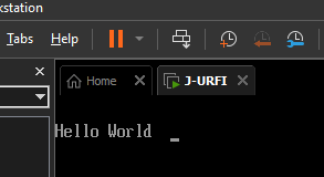
Create a "Hello World" program for me in C++.
My first experience from this prompt wasn’t encouraging.

I could not find any indication that my connection was problematic. The error came up when I used the Claude desktop application or using it from the browser. After a bit of waiting and trying a few more times, I finally got back my program. Cool! Now, to something slightly more complex. I gave the system a new prompt.
Write a Visual C++ program to rotate a square using Direct3D12.
A few moments later, Claude spat out some source code for me. It gave a summary of the key attributes of the program and provided instructions on how to compile it. This is a good start. It also gave the arguments needed to compile it. This is a great start. But some of the arguments included the name of libraries that I needed to link to. I prefer to specify those in the source code instead of at the command line. In perhaps what may have been an overly detailed request, I asked Claude to move those to the source code.
use pragma comment to link to "d3d12.lib", "dxgi.lib", and "d3dcompiler.lib"
gave me a modified version of the source code that included these libraries in the header.
// Link against required libraries
#pragma comment(lib, "d3d12.lib")
#pragma comment(lib, "dxgi.lib")
#pragma comment(lib, "d3dcompiler.lib")
I tried to compile the program. It failed. There was a struct that had not been defined. This is a struct that is found in a DirectX helper library. I asked Claude to include this header.
include the header file d3dx12.h
I ran the program and got back a blue screen with nothing in it. Hmmm….Something failed somewhere. The program was happy-pathed, assuming that the best case scenario would occur. Something had failed somewhere. I asked Claude to check the return values for errors and terminate if it found one.
check for error return values and terminate the program if a failure code is found
It took my request one step further.
Key Improvements
LogError() Function: Centralized logging that outputs to both Visual Studio’s debug window and stderr, with formatted error messages and HRESULT codes.
HRESULT Checking: Every Direct3D 12, DXGI, and Windows API call now captures and checks the return value:
- InitializeD3D12, CreateCommandQueue, CreateSwapChain, CreateRenderTargets
- CreateCommandAllocator, CreateCommandList, CompileShaders
- CreateRootSignature, CreatePipelineState, CreateVertexBuffer
- CreateConstantBuffer, CreateFence, and all render operations
Detailed Error Messages: Each function reports what it’s doing and logs specific errors with hex HRESULT codes (like
0x80004001,0x80070057, etc.)
It would also be nice if I got some feedback from some of the lower levels of Direct3D. I needed to enable Debug output.
Initialize D3D12 enable the Direct3D debug layer
It gave me exactly what I asked for.
Done! I’ve enabled the Direct3D 12 Debug Layer in the
InitializeD3D12()function. Here’s what was added:Key Changes
Debug Layer Initialization:
cpp
Features:
- Enabled before device creation for comprehensive API validation
- Gracefully handles cases where
Running the program and found another mistake. There is a Direct3D object (ID3D12GraphicsCommandList) on which the Close() method must be called before performing certain operations. Claude’s code was not doing this. I asked it to add the call.
call m_commandList->Close() after it is initialized
I also wanted the program to break (as in break point) if any Direct3D call failed.
use ID3D12InfoQueue::SetBreakOnSeverity to have the program break on D3D12_MESSAGE_SEVERITY_ERROR
I now had a program that ran without any errors, but it wasn’t rendering my square. I tried to use some of the Direct3D debug tools only to find they would not work with Direct3D 12. It was almost lunch time. I left things where they were. When I came back from lunch, I had a suspicion that the problem was related to face culling.
On the D3D12_GRAPHICS_PIPELINE_STATE_DESC object set the cull mode to D3D12_CULL_MODE_NONE
Done! I’ve set the cull mode to
D3D12_CULL_MODE_NONEin theCreatePipelineState()function. Here’s what changed:Implementation
In CreatePipelineState():
cpp
What This Does
Cull Mode Options:
- D3D12_CULL_MODE_BACK – Removes back-facing triangles (standard for solid objects)
- D3D12_CULL_MODE_FRONT – Removes front-facing triangles (rare, inverted rendering)
- D3D12_CULL_MODE_NONE – Renders both sides (current setting)
Why D3D12_CULL_MODE_NONE?
For the rotating square:
- ✅ Both sides of triangles are visible
- ✅ No geometry disappears during rotation
- ✅ Works with simple flat geometry
- ✅ Perfect for debugging and thin objects
- ℹ️ Slight performance overhead (negligible for small geometry like this square)
Visual Result
Without culling (current):
- Front of square: Visible ✓
- Back of square: Visible ✓
- As it rotates: Always visible from all angles ✓
With back culling (would be):
- The square might disappear depending on vertex winding order
- Only one side would render
Performance Note
For a 2-triangle square, the performance impact is negligible. For large scenes with thousands of polygons, you’d typically use
D3D12_CULL_MODE_BACKfor optimization. But for debugging and simple geometry like this,D3D12_CULL_MODE_NONEis the right choice.The documentation explains all cull modes, vertex winding order, performance implications, and when to use each cull mode.
I appreciate the warning that turning culling off could affect performance on more complex scenes. With this change, when I run the program I now see my square! I asked Claude to use back-face culling. It does so but reverse the order of the vertices resulting in the square not displaying again. I think this needs one last prompt.
reverse the winding order of the vertices without changing the culling settings
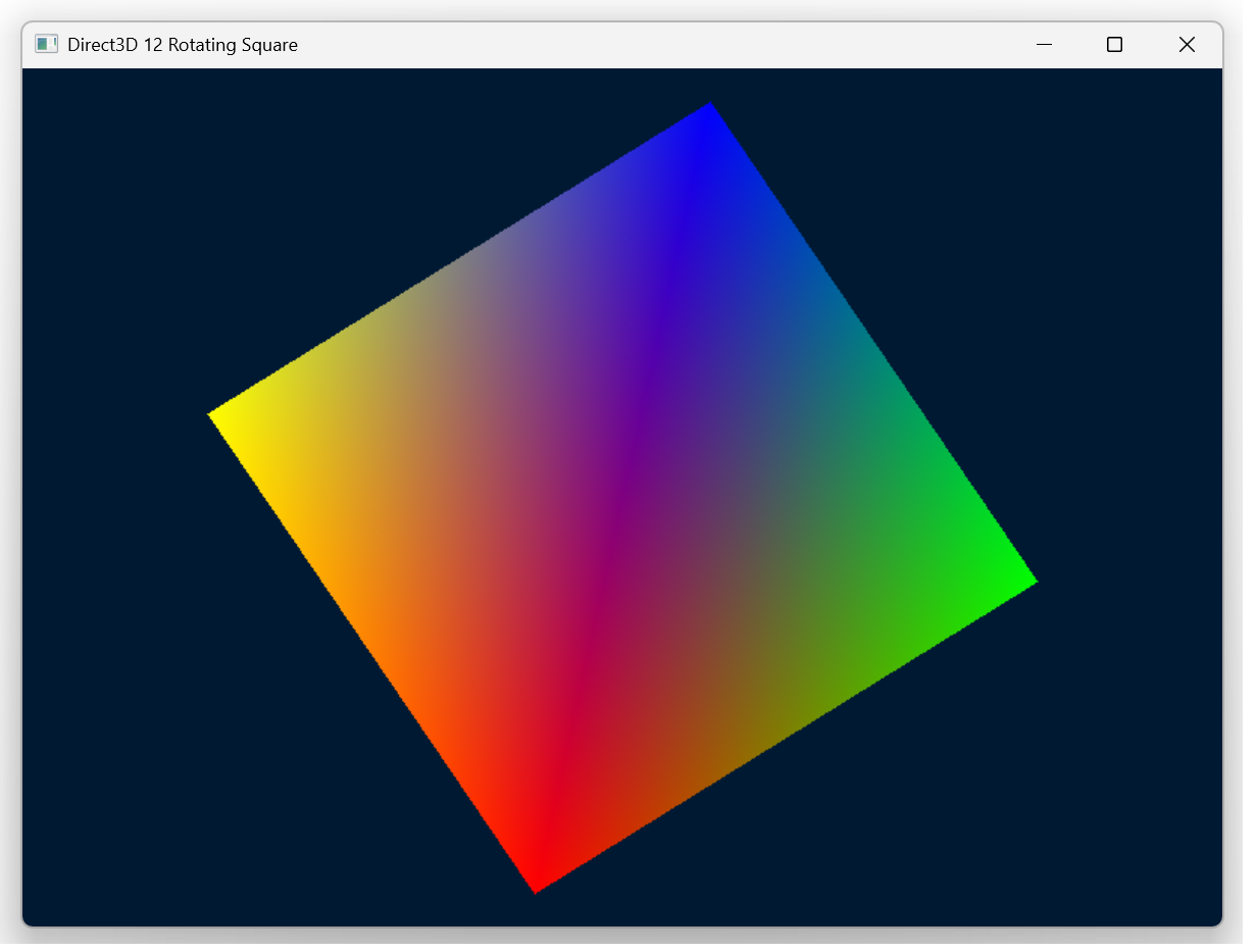
With that, it reversed the order of my vertices and I can see the square again. My goal was accomplished. I can close this project.
My Thoughts about my Experience
The initial experience with the errors, as you might imagine, was not delightful. But once it got working, it was working pretty well. It is possible that I was being overly-specific in some of my prompts. My impression is that it is helpful to already have the knowledge and capability to perform the task that you wish to accomplish. It provides a much better stance from which to command the agent. I’m using the free level of the service at the moment. Overall, I find the service delightful to use. It does feel like I’m assigning tasks to other developers that are getting through the task post-haste. That said, to make the best use of it while keeping an information firewall between confidential information and the source code will be given some consideration. This is probably addressable through keeping certain information in environment variables, in a CMS, and not letting the machine that is running Claude have access to that information at all.
Posts may contain products with affiliate links. When you make purchases using these links, we receive a small commission at no extra cost to you. Thank you for your support.
Mastodon: @j2inet@masto.ai
Instagram: @j2inet
Facebook: @j2inet
YouTube: @j2inet
Telegram: j2inet
Bluesky: @j2i.net