Many of the people with which I work are classified as being technical or creative (though there is a spectrum between these classifications). On many projects, the creative workers design UIs while the technical people transform those designs into something that is working. I’m a proponent of empowering those that are creating a design with the ability to implement it. This is especially preferred on projects where a design will go through several iterations.
I was recently working on a project for which there would be a menu with a map of a building. Clicking on a room in the map would take the user to web page that had information on the room. I had expected the rooms on the map to generally be rectangular. When I received the map, I found that many of the rooms had irregular shapes. HTML does provide a solution for defining shapes within the image that are clickable through Image Maps. I’ve never been a fan of those, and for this specific project I would not be able to ask the creatives to update the image map. I decided on a different solution. I can’t show the picture of the map that was the image being displayed. As an example, I’ll use a picture of some lenses that are sitting in the corner of my room.
Collection of Lenses
Let’s say I wanted someone to be able to click on a lens and get information about them. In this picture, these lenses overlap. Defining rectangular regions isn’t sufficient. I opened the picture in a paint program and applied color in a layer over the objects of interest. Each color is associated with a different object classification. Image editing isn’t my skill though. The result looks rough, but sufficient. This second image will be used in an HTML page to figure out which object that someone has clicked on. I’ll have a mapping of these color codes to objects.
When a user clicks on the real image, the pixel color data is extracted from the associated image map and converted to a hex string. To extract the pixel data, the image map is rendered to a canvas off-screen. The canvas’s context exposes methods for accessing the pixel data. The following code renders the image map to a canvas and sets a variable containing the canvas 2D context.
function prepareMap(width, height) {
    var imageMap = document.getElementById('target-map');
    var canvas = document.createElement('canvas');
    canvas.width = width;
    canvas.height = height;
    var canvasContext = canvas.getContext('2d');
    canvasContext.drawImage(imageMap, 0, 0, imageMap.width, imageMap.height);
    areaMapContext = canvasContext;
}
I need to know the position of the image relative to the browser’s client area. To retrieve that information, I have a method that recurses through the positioning containers for the image and accumulates the positioning settings to a usable set of coordinates.
function FindPosition(oElementArg) {
    if (oElementArg == undefined)
        return [0, 0];
    var oElement = oElementArg;
    if (typeof (oElement.offsetParent) != "undefined") {
        for (var posX = 0, posY = 0; oElement; oElement = (oElement.offsetParent)) {
            posX += oElement.offsetLeft;
            posY += oElement.offsetTop;
        }
        return [posX, posY];
    }
    return [0.0];
}
The overall flow of what happens during a click is defined within mapClick in the example code. To convert the coordinates on which someone clicked (relative to the body of the document) to coordinates relative to the image, I only need to subtract the offsets that are returned by the FindPosition function. The retrieved colorcode for the area on which the user clicked can be used as an indexer on the color code to product identifier mapping. The product identifier is used as a indexer on the product identifier to product data mapping.
function mapClick(e) {
    var PosX = e.pageX;
    var PosY = e.pageY;
    var position = FindPosition(targetImage);
    var readX = PosX - position[0];
    var readY = PosY - position[1];

    if (!areaMapContext) {
        prepareMap(targetImage.width, targetImage.height);
    }
    var pixelData = areaMapContext.getImageData(readX, readY, 1, 1).data;
    var newState = getStateForColor(pixelData[0], pixelData[1], pixelData[2]);
    var selectedProduct = productData[newState];
    showProduct(selectedProduct);
}
Once could simplify the mappings by having the color data map directly to product information. I chose to keep the two separated though. If the color scheme were ever changed (which I think is very possible for a number of reasons) I thought it better that these two items of data be decoupled from each other.
You can find the full source code for this post on GitHub at this url. Because of security restrictions in the browser, you must run this code within a local HTTP server. Attempting to run it from the file system will fail due to limitations in how an application can use the data it loads when loaded from a local file. I also have brief videos on my social media account to walk through the code.
Posts may contain products with affiliate links. When you make purchases using these links, we receive a small commission at no extra cost to you. Thank you for your support.
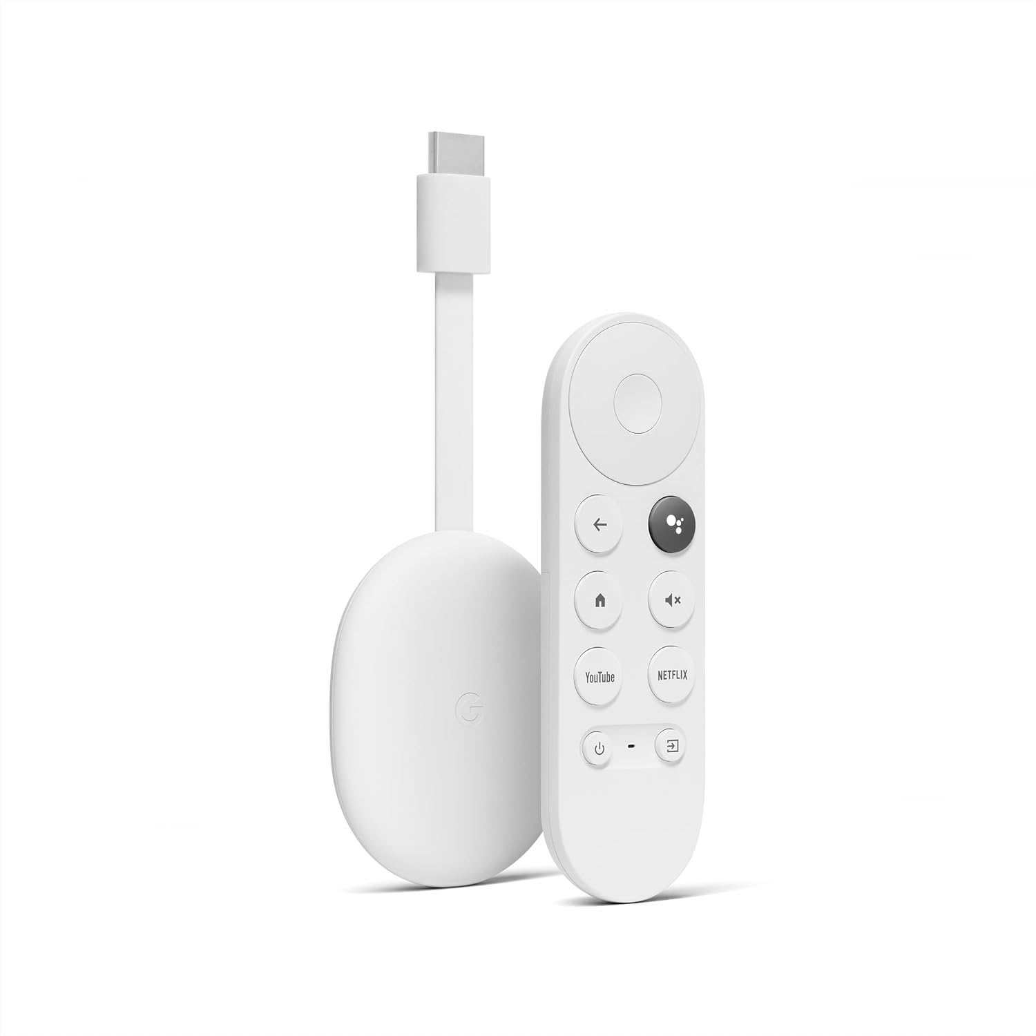
Recently, Google announced that it will be bringing Stadia to an end. Stadia was Google’s game streaming service. With the purchase of a controller and a Chromecast, users could take advantage of GPUs in the cloud to play their games. To use the service, there was both a monthly fee for access and games had to be individually purchased. The cancellation comes at a time closely following reports that Sundar Pichai told employees of plans for cost cuts to make Google more profitable[src]. Google also released a blog post [src] stating that the service didn’t get the traction they had hoped.
A few years ago, we also launched a consumer gaming service, Stadia. And while Stadia’s approach to streaming games for consumers was built on a strong technology foundation, it hasn’t gained the traction with users that we expected so we’ve made the difficult decision to begin winding down our Stadia streaming service.
I’m in possession of a number of Stadia units myself. Speaking only for myself, it didn’t have faith in the product. I carry skepticism of online-only games, having lost games to smaller incidents before. One of the first XBox 360 games I had purchased online became inaccessible to my other Xbox’s when the publisher left the store. I’ve had other games that installed locally that have become less functional or completely non-functional because a server was taken offline. When I do purchase an app or a game, I do so knowing that the app could become unusable and unavailable. I don’t mind paying small amounts for what I see as temporary access to a game or app. But paying $60 for a game that could essentially evaporate out of my account was not comfortable for me. Nor was the ongoing 10 USD/month I’d pay for access to the game.
I don’t know why other people might not have jumped on board. Especially with the component shortage making the acquisition of Xbox and PlayStation challenging. Those units have been out for two years and we still are not in a place where someone can walk into a retail store and have high confidence that there will be a unit on the shelf to pickup and purchase.
What does this all mean for those that may have purchased games? The outcome financially is most favourable. They are getting a refund from Google.
We’re grateful to the dedicated Stadia players that have been with us from the start. We will be refunding all Stadia hardware purchases made through the Google Store, and all game and add-on content purchases made through the Stadia store. Players will continue to have access to their games library and play through January 18, 2023 so they can complete final play sessions. We expect to have the majority of refunds completed by mid-January, 2023. We have more details for players on this process on our Help Center.
The Chromecasts of course are still very usable and functional. The controllers themselves are, as far as I can tell, e-waste now. Out of curiosity, I looked up the Stadia in the Google Store. It is still listed on the store with no ability to make a purchase.
I very much wish that Google would release the source code or some other information so that the community could make the controllers useful. But since they are giving full refunds, I don’t think that they will be doing much more. The only things that people might have lost is their saved games (for games that do not support progress cross play, as Destiny did). According to a post on Reddit, Google did acknowledge the desire for the controllers to remain useful after the shutdown. But no promises were made [src].
Posts may contain products with affiliate links. When you make purchases using these links, we receive a small commission at no extra cost to you. Thank you for your support.
I’m back from taking a break. I’ve been working on a number of projects that culminated a crunch-time scenario where there was lots to get done before I went on a vacation for which I would have no computer and an Internet connection that would range from flaky-to-none. When going on trips I often bring some movies with me to watch when I’m taking a break and retreating to my lodging. For this trip, I did something a bit different than usual. Instead of copying my media directly to my mobile device, I decided I would copy it to a Raspberry Pi and set it up as a movie streaming server. (More on elements of my particular scenario at the end of this post) Early last year I had posted something on using Express and NodeJS for streaming. For this trip, I copied that to a Pi that had a lot of storage and did some other things to prepare it for my environment. These included:
Setting up the Pi as a Wireless Access Point
Setting my Application to Run on Boot
Adding the Ability to Upload files
While I didn’t perform these changes during my trip, I realized there was some other functionality I wanted this solution to have, including
Converting videos of other formats to MP4
Ensuring the MP4’s metadata was arranged for streaming
Adding some service to convert uploaded files as needed
Many of these changes could be topics of their own. Let’s talk about uploading files.
Uploading a File with express-fileupload
My first solution for uploading a file was to make a simple web form allowing a file to be selected and add a router to my web application to handle file uploads. I’ll start off telling you that this didn’t work. Skip ahead to the next section if you don’t want to read about this initial failed attempt. The webform itself is simple. A minimalist version of it follows.
On the server-side, I added the a router to accept my file uploads and write them to a target folder. Upon receiving the bits of the file, I’m writing it to a designated folder preserving the original file name.
//Do not use. For demonstration purposes only. While this
//appears to work. But the entire file is loaded to memory
//before being written to disk. I've found with large files
//this can easily slow down or halt the Pi. Use the router

const express = require('express');
const router = express.Router();

router.post('/', async(req,res) => {
	try {
		if(!req.files) {
			console.log(req.body);
			res.send({
				status: false,
				message: 'No File'
			});
		} else {
			let video = req.files.video;
			video.mv('./uploads/' + video.name);
			res.send({
				status: true,
				message: ' File Uploaded',
				data: {
					name: video.name,
					mimetype: video.mimetype,
					size: video.size
				}
			});
		}
	} catch(err) {
		res.status(500).send(err);
	}
});
module.exports = router;
Testing it out on a small file, it works just fine. Testing it out on a large file locks up the Pi. The issue here is that **all** of the file must be loaded to memory before it is written to storage. The files I was uploaded were feature-length high-definition videos. I tried uploading a 4.3 gig video and saw the Pi progress from less responsive to all responsive. This wasn’t going to work for my needs.
Uploading and Streaming to Storage with Busboy
Instead of using express-fileupload I used connect-busboy. Using Busboy I’m able to stream the bits of the file to storage as they are being uploaded. The complete file does **not** need to be loaded to memory. When the upload form sends a file, the busboy middleware makes the file’s data and meta-data available through the request object. To save the file, create a file stream to which the data will be written and pipe the upload (busboy) to the file storage stream.
With this in place, I have a working upload feature. I don’t want to stop there though. FFMPEG runs on the Pi and I may take advantage of this to do additional transformations on media to prepare it for streaming. I’m going to add code for handling this processing next.
I only brought the Pi for movies, but I ended up using it for a lot more. I had an iPhone and an Android phone with me on the trip. I managed to fill up the memory on my iPhone and needed a place to move some video. The Android phone had plenty of space, but there was no direct method to transfer data between the two devices. At one point I also wanted to edit video using Adobe Rush, only to find that Adobe doesn’t allow Rush to be installed on Samsung’s latest generation of phones at this time. My iPhone had Rush, thus I had to get information transferred from my Android Phone to my iPhone to do this.
Had these use cases come to mine I probably would have acquired a USB adapter for my Phone (the Android phone will connect to my USB-C drives with no special adapters needed). I’m sure there are apps that could be used to bridge this gap, but my iPhone has no coverage when I’m out of the country. I didn’t have access to try out such apps. Some part of me feels that it is a bit silly that data can’t move between these two systems without some intermediary, such as another computer, or dongle and drives. But given that we are still not at a point where media in text messages is reliably transferred without quality loss it isn’t surprising.
Given more time, I might make an app specifically for transferring data between devices in the absence of a common network. (This is not something I am promising to do though).
Posts may contain products with affiliate links. When you make purchases using these links, we receive a small commission at no extra cost to you. Thank you for your support.
Photography is among my interests. I decided to experiment with time lapse photography using plants. To create a time lapse video, someone needs a camera on which they can take photos at timed intervals and a software to assemble those photographs together as a video. There are many solutions for doing this. Over time I will try out several different software programs, cameras, setups, and subjects. For this first attempt, I used a GoPro. I have a GoPro 5. It is an older model. Currently, the most recent GoPro version available is a GoPro 10. All of these models have time lapse photography settings built into the device. You choose your camera settings; select the time interval between photographs; aim the camera at your subject; and let it get started. With these cameras you can also specify that you are doing a video and it will assemble the photos into a video for you.
When doing a time lapse shot, you want to leave the setup undisturbed. But you will also want to know how things look so that you can make corrections. To this end, I let the GoPro run for a few hours and stopped it to look at the results. When I did this, I found that my original settings of taking a photo once a second was too frequent. It would fill up the memory card that I was using too fast. I also found that i didn’t like my original angle. I made adjustments, let another test run for another hour, and was content. I set things up and let them run. The results were okay overall, but there was still plenty of room for improvement. The first item of improvement was in the lighting. While aesthetically I liked the look, the light wasn’t sufficient for the plant. In my timelapse you will see that the plants grow up long and skinny. This is something that plants would do while underground with little light exposure. They would do this until they get sufficient light and then transition from growing up to growing out. Because of the insufficient lighting, these plants used a lot of their resources trying to grow up to get more light.
Towards the end of my timelapse, I pulled out one of my DSLRs. (I feel that DSLRs are ancient given the major camera manufacturers have transitioned to mirrorless. But it still works, and I keep using it). I have an intervalometer for my camera. This is a timing device that can be used to trigger camera. I set it up for 10 second interviews, just like the GoPro and let it run during the last day of the 10 days that it took for me to get my time lapse shots. The results were much better. Comparing the two, the DSLR will by my go-to device for time lapse shots. That’s not to say the GoPro is out. The GoPro is much more tolerant to various conditions, especially outdoor conditions. I’ll be using it for some outdoor time lapse shots fairly soon. Though the results will be far off in the future.
One of the issues here is that the lighting conditions that give the photo the look that I want might not be the conditions under which the plant can thrive. I started to imagine solution, and I thought a solution that may work is having a light that turns off of changes brightness in sequence with the photos. Full lighting conditions would be applied most of the time. But the moment just before to just after the shot being taken, the dimmer lighting conditions could be used. I’ve got a DMX controller and thought about using it. But that could be over kill. I thought about using a relay controlling a power source. But after a lot more thinking, I realized I already have a solution. My hue lighting. The Phillips hue lights are controllable via rest calls. I could have a pi dedicated to controlling the lights of interest.
The light switching must be coordinated with the camera. My intervalometer would not work for this. While I could probably get a working time sequence up front, over the course of days the intervalometer and the light sequencing could drift out of sync with each other. I need to have the Pi control the camera too. I’ve written before on controlling Hue lighting from the Pi. I think that could be used here. Now as soon as I get free time from work and other obligations, I’ll be looking into controlling the digital camera from a Pi. Some of the libraries that I’ve looked at appear to be capable of controlling both the traditional DSLRs and the more modern mirrorless cameras.
I’ve gotten some seeds for corn, okra, and peppers planted now. Once they sprout, I’ll start my next time lapse with a more advanced setup.
For me the options for adding a screen to a Raspberry Pi have always come with a bit of dissatisfaction. This isn’t because of any intrinsic flaws in the designs. The Pi, having its own thickness which has contributed to solutions that have form factors that are not quite my preference. This started to change with the release of the Raspberry Pi Computer Modules. With the Raspberry Pi Compute Module 4 I see some satisfying solutions. One of the solutions has available a plan for a 3D printable case. Another comes already encased. I chose a solution that already has a case because I don’t have a 3D printer and I’ve had mixed results in using third-party printers. The solution that I selected is the Seeed Studio reTerminal.
Video covering the Seeed Studio reTerminal
Before speaking on it more, I want to point out that this case does not have a battery. If you are seeking a solution with a battery, then you may want to consider the solution with the 3D print designs and alter it to hold a battery.
The unit is sold with a Raspberry Pi Compute Module 4 (CM4) included. Right now, the unit is sold with the CM4 that has Wi-Fi, 4 gigs of RAM, and 32 Gigs of eMMC. This is great, as it is near impossible to get a CM4 by itself in present-day times. The packaging for the unit uses more flexible wording saying “Up to 8GB RAM/Up to 32GB EMMC” suggesting that at some point they may see the unit with other variants. The only indication of what CM4 module is in the box is a sticker with the barcode that spells out the CM4 version (CM4104032).
The display on the unit itself is 720×1280 pixels. It sounds like I said these dimensions reverse. I haven’t. Using the direction in which the pixels are refreshed, the first line of scan is the left area of the screen and it works its way to the right. This differs from conventional displays that start at the top and work their way down. Accessible through the case is gigabit Ethernet, 2 USB 2.0 ports, the Pi 40-pin header, and an industrial high-speed expansion interface. This unit was designed with industrial applications in mind. Though I won’t be paying attention to this industrial interface. The case also has a real-time clock, a cryptographic coprocessor, a few hardware buttons including a button to power the unit on, an accelerometer, and a light sensor. Out of the box the software needed for this additional hardware is preinstalled. Should you choose to reinstall the operating system yourself, you will need to install the software and drivers for the additional hardware manually.
Component Layout Diagram from Seeed Studio
The packaging for the unit contains extra screws, a screwdriver, and the reTerminal unit itself. On the lower side of the unit is a connector for a 1/4-inch screw. This is the same sized screw used by many camera tripods. I’m using one of the mini desktop tripods for my unit. To power the unit on all that is needed is to connect power to the USB-C connector on the left side of the reTerminal.
The unit does not ship with an on-screen keyboard installed. For initial setup, I will want to have at minimum a USB-C power supply and a keyboard. If you do not have a mouse, you could use the touch screen just fine.
reTerminal Specific Hardware
I’ve mentioned a number of hardware items contained within the reTerminal, such as the custom buttons. Accessing the additional hardware and interfaces is easier that I expected. The four buttons on the front have been mapped to the keyboard keys A, S, D, and F. If you would like to map these to different keys, they can be set through /boot/config.txt. Within that file is a line that looks similar to the following.
The hex numbers are ASCII codes for the characters these keys will generate. You can change these as needed.
LEDs and Buzzer
There are four positions for LEDS at below the screen of the unit. Two of those positions have LEDs that are controllable through software. The positions are labeled STA and USR. USR has LED 0 (green). Position STA las LEDS 1 (red) and 2(green). Because of the two LEDs behind position STA, the perceived color of the position can range from green to yellow to red. Control of the LEDs is available through the file system. In the directory /sys/class/leds are the subdirectories usr_led0, usr_led1, and usr_led2. Writing a text string with a number between the range of 0 and 255 to a file named brightness will set the brightness of the LED with 0 being off and 255 being full brightness. Note that root access is needed for this to work.
According to documentation, the brightness of the LEDs is changed with this number. But in practice, each led appear to be binary. I don’t see any difference in brightness for a value of 1 and of 255.
The Buzzer is treated like the LED, but only has a “brightness” level ranging from 0 (off) to 1. The name of the device directory for the buzzer is /sys/class/leds/usr_buzzer. Like with the LEDs, write to a file named brightness.
Real Time Clock
The real-time clock is connected to the I2C interface of the CM4. The command line utility hwclock works with the clock.
Light Sensor
The light sensor is exposed through the file path /sys/bus/iio/devices/iio:device0. Reading from this file will expose the brightness value.
Accelerometer
The accelerometer in the unit is a ST Microelectronics LIS3DHTR. This hardware can be used to automatically change the screen orientation, or for other applications. To see it in action, you can use the evtest tool that Seeed Studio preinstalled on the device. Running evtest and selecting the index for the accelerometer hardware will result in it displaying the readings for each axis.
My Setup
As per my usual, after I had the Pi up and running there were a few other changes that I wanted to apply.
For testing much of the above-mentioned hardware, root access is needed. I would prefer to avoid using root access. I first tried to grant permission on the needed files to the user pi. Ultimately, this doesn’t work as planned. The file paths are sysfs paths. This is part of a virtual file system used for accessing hardware. It gets recreated on each reboot. Changes made do not persist. But if you wanted to grant permissions that are available until the next reboot, you could use the following. Otherwise, you’ll need to run your applications that use this additional hardware as root.
#enter interactive root session
sudo -i
#navigate to the folder for LEDs and the buzzer
/sys/class/leds/
#grant permission to the pi user for the brightness folder
chown pi usr_led0/brightness
chown pi usr_led1/brightness
chown pi usr_led2/brightness
chown pi usr_buzzer/brightness

#grant permission to the light sensor
chown pi /sys/bus/iio/devices/iio:device0

#exit the root session
exit
Some of the hardware uses the SPI and I2C interfaces. Using the Raspberry Pi Config tool, make sure that these interfaces are enabled.
Install the tool for input event viewing. The tool is named evtest.
sudo apt-get install evtest -y
Once installed, run evtest. Note that even if you are using SSH to enter commands into your terminal that this tool still works. The tool will list the input devices and prompt you to select one.
 $ evtest
No device specified, trying to scan all of /dev/input/event*
Not running as root, no devices may be available.
Available devices:
/dev/input/event0:      Logitech K400
/dev/input/event1:      Logitech K400 Plus
/dev/input/event2:      Logitech M570
/dev/input/event3:      gpio_keys
/dev/input/event4:      ST LIS3LV02DL Accelerometer
/dev/input/event5:      seeed-tp
/dev/input/event6:      Logitech K750
/dev/input/event7:      vc4
/dev/input/event8:      vc4
Select the device event number [0-8]: 3
The actual order and presence of your options may vary. In my case, you can see the devices associated with a Logitech Unify receiver that is connected to the device. The hardware buttons that are on the device are represented by the device gpio keys. For me, this is option 3. After selecting three, as I press or release any of these buttons, the events print in the output. Remember that by default these buttons are mapped to the keys A, S, D, and F. This is reflected in the output.
Input driver version is 1.0.1
Input device ID: bus 0x19 vendor 0x1 product 0x1 version 0x100
Input device name: "gpio_keys"
Supported events:
  Event type 0 (EV_SYN)
  Event type 1 (EV_KEY)
    Event code 30 (KEY_A)
    Event code 31 (KEY_S)
    Event code 32 (KEY_D)
    Event code 33 (KEY_F)
    Event code 142 (KEY_SLEEP)
Properties:
Testing ... (interrupt to exit)
Event: time 1651703749.722810, type 1 (EV_KEY), code 30 (KEY_A), value 1
Event: time 1651703749.722810, -------------- SYN_REPORT ------------
Event: time 1651703750.122811, type 1 (EV_KEY), code 30 (KEY_A), value 0
Event: time 1651703750.122811, -------------- SYN_REPORT ------------
Event: time 1651703750.832809, type 1 (EV_KEY), code 31 (KEY_S), value 1
Event: time 1651703750.832809, -------------- SYN_REPORT ------------
Event: time 1651703751.402797, type 1 (EV_KEY), code 31 (KEY_S), value 0
Event: time 1651703751.402797, -------------- SYN_REPORT ------------
Event: time 1651703751.962817, type 1 (EV_KEY), code 32 (KEY_D), value 1
Event: time 1651703751.962817, -------------- SYN_REPORT ------------
Event: time 1651703752.402812, type 1 (EV_KEY), code 32 (KEY_D), value 0
Event: time 1651703752.402812, -------------- SYN_REPORT ------------
Event: time 1651703753.132807, type 1 (EV_KEY), code 33 (KEY_F), value 1
Event: time 1651703753.132807, -------------- SYN_REPORT ------------
Event: time 1651703753.552818, type 1 (EV_KEY), code 33 (KEY_F), value 0
Event: time 1651703753.552818, -------------- SYN_REPORT ------------
Since we are speaking of evtest, exit it with CTRL-C and run it again. This time select the accelerometer. A data stream of the accelerometer values will fly by. These are hard to visually track in the console. But if you reorient the device, if you are able to track one of the readings, you will see it change accordingly.
Event: time 1651705644.013288, -------------- SYN_REPORT ------------
Event: time 1651705644.073140, type 3 (EV_ABS), code 1 (ABS_Y), value -18
Event: time 1651705644.073140, type 3 (EV_ABS), code 2 (ABS_Z), value -432
Event: time 1651705644.073140, -------------- SYN_REPORT ------------
Event: time 1651705644.133259, type 3 (EV_ABS), code 1 (ABS_Y), value 18
Event: time 1651705644.133259, type 3 (EV_ABS), code 2 (ABS_Z), value -423
Event: time 1651705644.133259, -------------- SYN_REPORT ------------
Event: time 1651705644.193161, type 3 (EV_ABS), code 0 (ABS_X), value 1062
Event: time 1651705644.193161, type 3 (EV_ABS), code 1 (ABS_Y), value 0
Event: time 1651705644.193161, type 3 (EV_ABS), code 2 (ABS_Z), value -409
Event: time 1651705644.193161, -------------- SYN_REPORT ------------
Event: time 1651705644.253290, type 3 (EV_ABS), code 0 (ABS_X), value 1098
Event: time 1651705644.253290, type 3 (EV_ABS), code 2 (ABS_Z), value -405
Event: time 1651705644.253290, -------------- SYN_REPORT ------------
Light Sensor
Getting a value from the light sensor is as simple as reading a file. From the terminal, you can read the contents of a file to get the luminance value.
I earlier described the screen as having a resolution of 1280×720. That isn’t quite correct. It is 720×1280. It might look like I just reversed the numbers. I did. Typically screens refresh from top to bottom. This screen refreshes from left to right. You can check this for yourself by grabbing a window and moving it around rapidly. Some screen tearing will occur exposing the way in which the screen is rendering. If you were to make a fresh install of Raspbian or Ubuntu, this will be more apparent because the screen will be oriented such that the left edge is the top of the screen and the right edge is the bottom. If you would like to manage the orientation of the display and external displays that the reTerminal is connected to, there is a screen orientation utility to install for managing the layout.
sudo apt-get install arandr -y
Future Expansion
I don’t give much weight to plans for future products in general since there is no guarantee that they will materialize. But I’ll reference what Seeed Studio has published. The “Industrial High-Speed Interface” connects to a number of interfaces on the CM4. This includes the interfaces for PCIe, USB 3.0, and SDIO 3.0. Seeed Studio says that it plans to make modules available for connecting to this interface, such as a camera module, speaker and mic array. PoE, 5G/4G modems, so on.
Posts may contain products with affiliate links. When you make purchases using these links, we receive a small commission at no extra cost to you. Thank you for your support.
While I enjoy being productive on my pi over SSH, there are times when I need to access the desktop environment. Rather then be bound to the display on which the Pi is connected (if it is connected to one, some of my Pis have no display) I decided to setup Remote Desktop on the Pi. Most of the computers that I use are Windows machines and already have a remote desktop client. (Note: another option is VNC). I did this for my Jetsons as well. While the same instructions often work on both the Jetson and the Pi, this is not one of the situations where that was the case. I have another entry coming on how to perform the necessary steps on the Jetson.
On the Pi, there are only a few steps needed. Like many installations, start with updating your packages. Open a terminal and enter the following commands.
sudo apt-get update
sudo apt-get upgrade
This could take a while to run depending on how long it has been since you last ran it and how many packages that there are to install. After it completes, use the following commands to install a remote desktop server to your Pi.
sudo apt-get install xrdp -y
sudo service xrdp restart
Once the installation is done, you need to get your Pi’s IP address.
ifconfig
You should see the addresses for your Pi’s network adapters listed. There will be several. My Pi is connected via ethernet. I need the address from the adapter eth0.
Response from ifconfig.
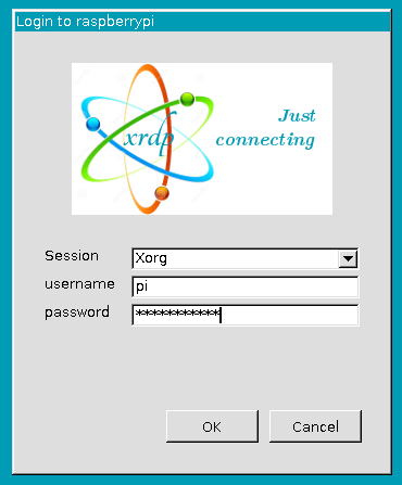
Once you have that information, you are ready co connect. Open the Remote desktop client in your computer and enter your Pi’s IP address as the identifier for the target machine. Once you enter it, you will be greeted with a second login screen that ask you information for the session your wish to start.
PI RDP Login
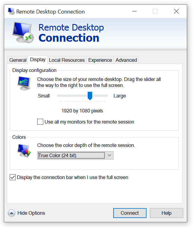
Leave the default setting of the Session as Xorg. Enter the user ID and password for your Pi. A few moments later you will see the Pis desktop. Note that while many remote desktop clients will default to using the resolution of your local computer’s display, you also have the option of setting a resolution manually. You may want to do this if you are on a slower network connection, or even if you just do not want your remote session to cover all of your local desktop.
Remote Desktop Client Resolution Settings
Posts may contain products with affiliate links. When you make purchases using these links, we receive a small commission at no extra cost to you. Thank you for your support.
Today was a nice day. The weather was sunny, but not hot and the sky was fairly clear. I already had my telescope in my car for plans that were not starting until after sunset. But I decided to do a bit of sun gazing while the sun was up. “Sun gazing” is a term that might raise a bit of concern since looking at the sun directly can be damaging to one’s vision. Don’t worry, I wasn’t doing that. I was using proper equipment. I grabbed some video clips from my gazing and shared them on my YouTube and Instagram accounts. This post gives further information about that video.
Acquired for the 2017 eclipse, I have a solar filter that covers my telescope’s opening. These filters block more than 99.9% of sunlight. A hole even as small as a pin head would render the filter unusable by letting too much light in. Without the filter, simply pointing the telescope at the sun could be damaging; there could be heat buildup inside the telescope, and whatever is on the viewing end of the telescope will suffer serious burns with exposure of only a moment.
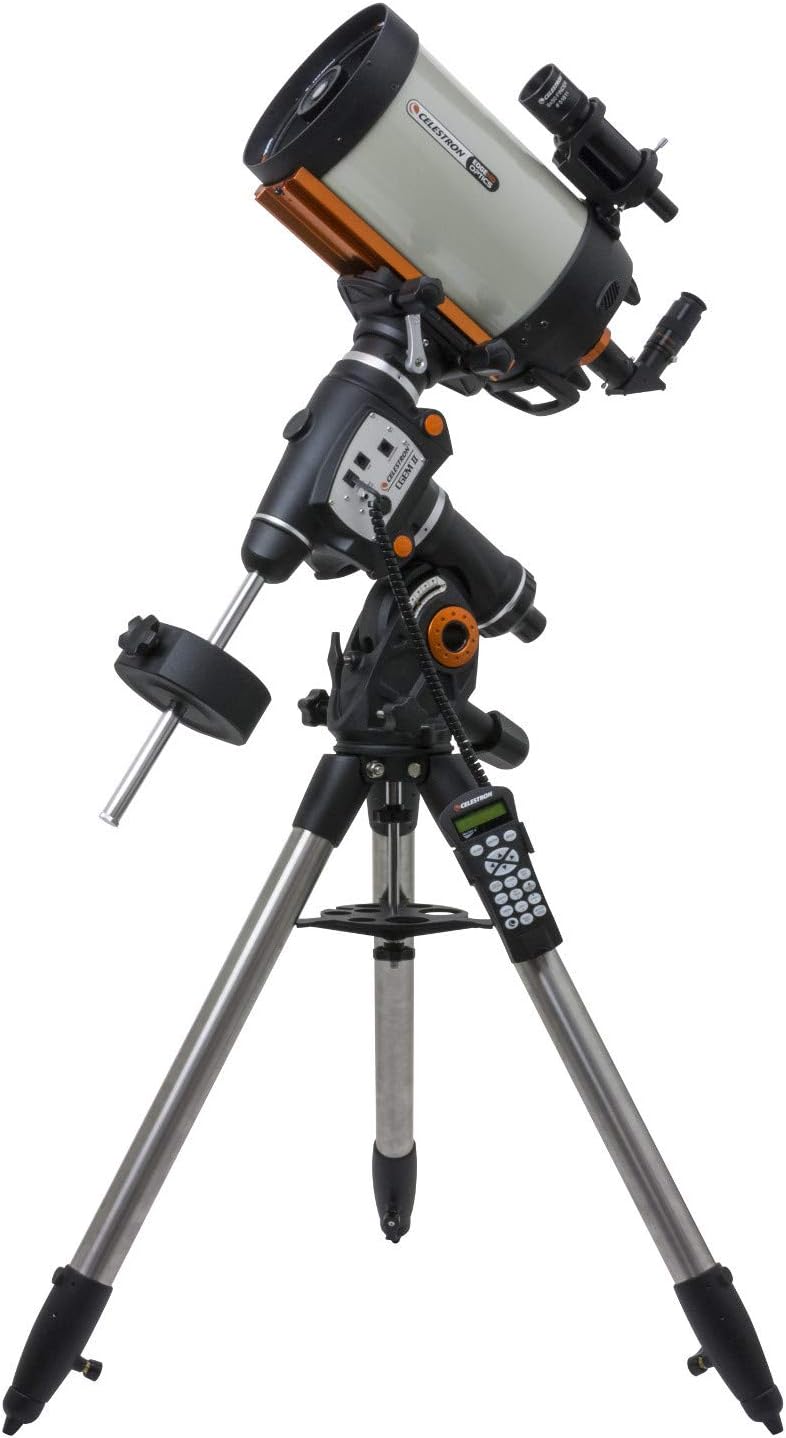
I have a couple of telescopes at my disposal, but that telescope on the motorized mount is generally preferred for a couple of reasons. One is that it automatically points at the planet, star, or nebula that I select from a menu in a hand controller (after some calibration). Another is that it will automatically adjust in response to the earth’s rotation. This last item might not sound significant, but it is! With my manual telescope, once I’ve found a heavenly body, the body is constantly rotating out of view. With proper alignment the body can be tracked by turning a single knob. But it can be a bit annoying when one looks away for a moment only to return and must hunt down the body of interest. The downside of the motorized mount is the weight and the need for electricity. My full motorized telescope setup is over 100 pounds. At home this isn’t a problem, as I can carry the full assembled setup in and out of my home and connect it to my house’s power. For usage in other locations, I must either bring power with me or have my car nearby to provide electricity.
CGEM II 800 Edge HD
My telescope is a much older unit. It is a Celestron CGEM 800. This specific model is no longer sold since it has been replaced with newer models. With the CGEM 800, there were additional accessories I purchased to add functionality that comes built into some other models. I added GPS to my telescope, which enables it to get the time, date, and the telescope’s location (all necessary information for the telescope to automatically aim at other bodies). I’ve also added WiFi to my telescope. With WiFi, I can control the scope from an app on a mobile device. For some scenarios, this is preferred to scrolling through menus on the two-line text only display on the scope’s hand controller.
While one won’t be viewing any sunspots with it, I also keep a set of eclipse glasses with my setup. I use these when aligning the telescope with the sun. While they are great for looking at the sun, you won’t be able to see anything else through them🙂. If you want to be able to see more details you would need a telescope that filters out specific wavelengths of light. The Meade Solarmax series are great for this. But they are also expensive and only useful for viewing the sun.
At this time of the year from where I live, there are only a few bodies from the solar system visible; the sun and the moon. If I were to use the telescope at 5AM I might be able to catch a glimpse of another planet just before the sun begins to wash out the quality of the image. Not something I’m interested in doing. I’ll take the telescope back out later in the year when there is an opportunity to see more.
On another YouTube channel someone mentioned they thought it would be cool if it were possible to control a telescope with a Raspberry Pi. Well, it’s possible. I might try it out. I’ve controlled my telescope from my own software before, and may try doing it again. Later in the year when the other planets are visible, it might be a great solution for controlling the telescope and a camera to get some automated photographs.
NVIDIA is holding a session on an introduction to Edge Computing. The introduction is said to cover fundamentals, how to integrate edge computing to your infrastructure, which applications are best deployed to the edge, and time for Q&A. The conference is at no cost. If you’d like to register for the conference, use this link.
Posts may contain products with affiliate links. When you make purchases using these links, we receive a small commission at no extra cost to you. Thank you for your support.
I go through a lot more SD cards than a typical person. I’m usually putting these cards in single board computers like the Jetson Nano or the Raspberry Pi and am using them there. I have a lot of these devices. These cards only occasionally fail. But with a lot of devices “occasional” is frequent enough for my rate of card consumption to be higher than that of a typical consumer. The easy solution to this is to just not use SD cards. At this point, the Pi can boot of USB drives. I’ve generally resisted this for reasons of æsthetics. I just don’t like the U-shapped USB connector (feel free to tell me how silly that is in the comments section).
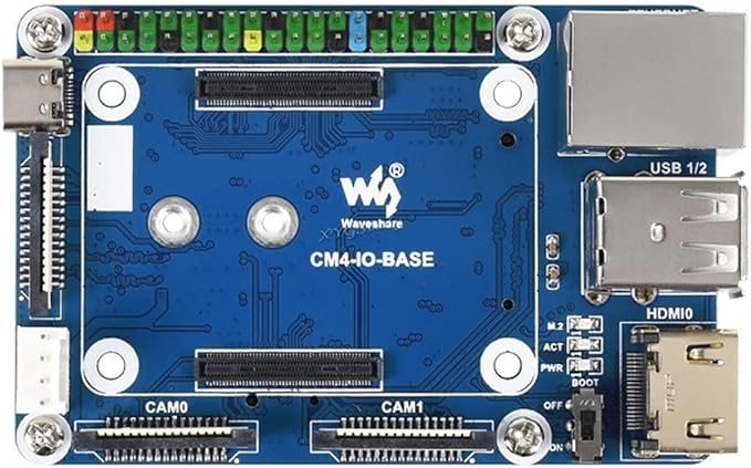
Enter the Raspberry Pi CM4. These modules have a PCIe interface, and you can select the board that has the hardware that you need. One of those boards is the WaveShare CM4-IO-Base. Among other hardware, this board has a PCIe M.2 keyed slot. There are two versions of this board, version A and version B. The main difference between these is the model B has a real time clock while the model A does not. Otherwise, these boards can be treated as identical
The CM4 IO-BASE-B that I am using sandwiched between acrylic cutouts.
The CM4-IO-BASE has screw holes in positions that are identical to what one would expect for a Raspberry Pi 4B. This makes it compatible with a number of bases on which you might want to attach the board. It does differ from the Pi 4B in that it uses a full-sized HDMI port placed where two of the USB ports are on the Pi 4B. At first glance, it appears to give you less USB and HDMI options than the Pi 4B. But two USB connections and an HDMI connection is available from the underside of the board. You would need to purchase the HDMI+USB Adapter to use those or interface to them directly.
The top of the board has two connectors for cameras, and a connector for an external display. The feature of interest to me was the M.2 PCIe interface on the underside of the board. I decided on a M.2 2242 drive with 256 Gigs of capacity. I’ve seen drives of this size up to 2-terabytes in size (for significantly more).
Getting the Pi to bootup from the NVME isn’t hard. The Compute Module that I have has eMMC memory; that’s basically like having an SD card that you can’t remove. Getting the Pi to boot from the NVME drive involves writing the Pi OS to the MVNE drive and changing the boot order on the Pi. For changing the boot order on the Pi I needed another Linux device. I used another Raspberry Pi.
Writing the image to the NVME drive works in the same way that you would write the image to any other SD card. I happen to have some external NVME drive enclosures removed the drive from one of them and placed my Pi’s NCME drive in it. The Raspberry Pi Imager accepted the drive as a target and wrote the OS to it. The tricky part was modifying the boot order on the CM4.
NVME Drive Enclosure
The default boot order on the CM4 is 0xF461. This is something that didn’t make sense to me the first time that I saw it. The boot order is a numeric value that is best expressed as a hex number. Each digit within that number specifies a boot device. The Pi will start with the boot device that is specified in the lowest hex digit and try it first, and then go to the next hex digit.
For the boot order 0xF461 the Pi will try to boot to devices in the following order.
0x1 – Boot from the SD Card/eMMC
0x6 – Boot from the NVME drive
0x4 – Boot from a USB mass storage device
0xF – Reboot the pi and try again.
If you have a CM4 with no memory, this means that all you need to do to ensure that the right boot order is followed is to ensure that you don’t have an SD card connected to the board. You are ready to boot from the NVME drive. That’s not my scenario, I had more work to do. I updated the boot order alongside the Pi’s firmware. The CM4 is usually in one of two modes. It is either running normally, in which case the boot loader is locked, or it is in RPI Boot mode, in which case the bootloader can be written to, but the OS isn’t running. The CM4 cannot update its own bootloader. To update the bootloader, another computer is needed. I think that the best option for updating the boot loader is another Linux machine. In my case, I chose another Raspberry Pi.
The Raspberry Pi can already b picky about the power supplies that it works with. I used a USB-C power supply from a Raspberry Pi 400 (the unit built into the keyboard) for the following steps. The usual power supply that I used with my Pi wasn’t sufficient for powering 2 Pis. You’ll find out why it needed to work for 2 Pis in a moment. I used a Raspberry Pi 4B for writting the firmware to the CM4. To avoid confusion, I’m going to refer to these two devices as Programmer Device and the CM4.
On the CM4-IO-BASE board there is a switch or a jumper (depending on hardware revision) for switching the Pi to RPI Boot Mode. Set a jumper on this pin or turn the switch to “ON”. Connect the CM4 to the Programmer Device with a USB-A to USB-C cable. From the programmer device, you will need to replicate a GitHub repository that has all of the code that you need. Open a terminal on the Programmer Device, navigate to a folder in which you want to replicate the code, and use the following commands to clone and build the code.
git clone https://github.com/raspberrypi/usbboot --depth=1
cd usbboot
make
The code is now downloaded or built. Enter the recovery folder and edit the file named boot.conf to change the boot order.
cd recovery
nano boot.conf
At the time of this writing, that file looks like the following.
[all]
BOOT_UART=0
WAKE_ON_GPIO=1
POWER_OFF_ON_HALT=0

# Try SD first (1), followed by, USB PCIe, NVMe PCIe, USB SoC XHCI then network
BOOT_ORDER=0xf25641

# Set to 0 to prevent bootloader updates from USB/Network boot
# For remote units EEPROM hardware write protection should be used.
ENABLE_SELF_UPDATE=1
The line of interest is BOOT_ORDER=0xf25641. The comment in this file already lets you know how to interpret this line. You want the NVME drive (0x6) to be the first drive. To make that happen, the digit 6 needs to be the last digit. Change it to 0xf25416. With this change, the CM4 will try to boot from the NVME first and the eMMC second. IF you ever want to switch back to using the eMMC you only need to remove the NVME drive. There is a file named pieeprom.original.bin. This is going to be written to the CM4. To ensure that the CM4 has the latest [stable] firmware, downloaded the latest version from https://github.com/raspberrypi/rpi-eeprom/tree/master/firmware/stable and overwrite this file. Looking in that folder right now, I see the most recent file is only 15 hours old and named pieeprom-2022-02-10.bin. To download this from the terminal, use the following command.
After the file is downloaded, run the update script to assemble the new firmware image.
./update-pieeprom.sh
Navigate to the parent folder. Run the rpiboot utility with the recovery option to write the firmware to the device.
sudo ./rpiboot -d recovery
This command should only take a few seconds to run. When it is done you should see a green light blinking on the Pi signaling that it has updated its EEPROM. Disconnect the CM4 from the Programmer Device. Remove the jumper or set the RPI Boot switch to off. Connect the Pi to a display and power supply. You should for a brief moment see a message that the Pi is expanding the drive partition. After the device reboots it will be running from the NVME.
At this point my primary motivation for using the CM4-IO-BASE-B board has been achieved. But there is some additional hardware to consider. If you have the CM4-IO-BASE model B then there is a real time clock to setup. For both models, there is fan control available for setup.
Real Time Clock Setup
The real time clock interfaces with the Pi via I2C. Ensure that I2C is enabled on your Pi by altering the file boot/config.txt.
sudo nano /boot/config.txt
Find the line of the file that contains dtparam=audio=on and comment it out by placing a # at the beginning of the line. Add the following line to config.txt to ensure I2C is enabled.
dtparam=i2c_vc=on
Reboot the device. With I2C enabled you can now interact with the RTC through code. Waveshare provides sample code for reading and writing from the clock. The code in its default state is a good starting point, but not itself adequate for setting the clock. The code is provided for both the C language and Python. I’ll bu using the C-language version of the code. To download the code, use the following commands.
sudo apt-get install p7zip-full
sudo wget https://www.waveshare.com/w/upload/4/42/PCF85063_code.7z
7z x PCF85063_code.7z -O./
cd PCF85063_code
After downloading the code, enter the directory for the c-language project and build and run it using the following commands.
cd c
sudo make clean
sudo make -j 8
sudo ./main
You’ll see the output from the clock. Note that the clock starts from just before midnight of February 28, 2021 and progresses into March 1. The code has the starting date hard coded. Let’s look at the code in main.c to see what it is doing.
You can see where the time is set with the functions PCF85063_SetTime_YMD and PCF85063_SetTime_HMS. Let’s update this to use the date/time that the system is using. Place the following two lines above those two functions. This will only grab the system time and print it.
    time_t T = time(NULL);
    struct tm tm = *localtime(&T);

    printf("***System Date is: %02d/%02d/%04d***\n", tm.tm_mday, tm.tm_mon + 1, tm.tm_year + 1900);
    printf("***System Time is: %02d:%02d:%02d***\n", tm.tm_hour, tm.tm_min, tm.tm_sec);
Build and run the program again by typing the following two lines from the terminal.
sudo make -j 8
sudo ./main
This time the program will print the actual current date and time.
USE_DEV_LIB
Current environment: Debian
DEV I2C Device
DEV I2C Device
***System Date is: 20/03/2022***
***System Time is: 19:19:06***
21-2-28 23:59:58
21-2-28 23:59:59
21-3-1 0:0:0
21-3-1 0:0:1
21-3-1 0:0:2
21-3-1 0:0:3
21-3-1 0:0:4
Let’s pass in this information to the calls that set the date and set the time. The information that we need is in the tm structure. Note that in this structure the first month of the year is associated with the value 0. Also note that the tm structure stores the year as the number of years since 1900, while the RTC stores the year as the number of years since 2000. We need to shift the value by 100 to account for this difference. The updated lines of code look like the following.
    printf("***System Date is: %02d/%02d/%04d***\n", tm.tm_mday, tm.tm_mon + 1, tm.tm_year + 1900);
    printf("***System Time is: %02d:%02d:%02d***\n", tm.tm_hour, tm.tm_min, tm.tm_sec);
	PCF85063_SetTime_YMD(tm.tm_year - 100,tm.tm_mon + 1,tm.tm_mday);
	PCF85063_SetTime_HMS(tm.tm_hour,tm.tm_min,tm.tm_sec);
When you run the program again, you’ll see the current time. But how do we know the RTC is really retaining the time? One way is to run the program again with the calls that set the time commented out. One would expect the RTC to continue to show the real time based on the previous call. I tried this, and the RTC was printing out times from 01-01-01. Why did this happen?
I’ve not completely dissected the code, but I did fine that a call to PCF85063_init() at the beginning of main resets the clock. I just commented this out. With that call not being made, the time is retained. I use this call when setting the clock though. I’ve altered the program to accept a command line parameter. If setrtc is passed to the program as a command line argument it will set the time on the RTC. If setsystem is passed as the parameter then the program will attempt to set the system time. Setting the system time requires root privileges. If you try to set the time with this program without running as root then the attempt will fail.
The final version of this code is available in my GitHub account. You can find it here.
Fan Control
There’s a difference in the version A and version B for the fan control. On version A the fan is connected to port 18. It can be turned on and off by changing the state of this pin. For version B the fan is controlled through the I2C bus. Example code is also provided for fan control on version B. To download the fan code for version-B use the following commands from the terminal.
sudo apt-get install p7zip-full
sudo wget https://www.waveshare.com/w/upload/5/56/EMC2301_code.7z
7z x EMC2301_code.7z -O./
cd EMC2301_code
To build the code, use the following commands.
cd c
sudo make clean
sudo make -j 8
sudo ./main
Let’s look at a highly abridged version of the code.
Fan control is straight forward. After some setup calls, the fan speed can be set by writing to EMC2301_writeTachoTarget(). The call to EMC2301_fetchFanSpeed() will read the current fan speed. Through repeated calls to this function you can see the acceleration of the fan when the speed is changed.
Other Hardware
Take note that a number of interfaces are disabled by default on the CM4. This includes the USB-C, the two DSI camera ports, and the display connector. If you need to use any of these, the resources page for this board has the information that needs to be added to the
Conclusion
Pi setup for this board was pretty easy. I’d definitely consider getting another one. If I had to do things all over again though I would double-check my cables. There was a moment when I thought things were not working because I wasn’t getting a video signal. It turns out that I had two HDMI cables close to each other that I thought was a single cable. I didn’t get a video signal because I had connected to a cable that was not terminating at my display (time to consider cable organization). This is a great board if you need a Pi that is close to the usual form factor but with more memory. I might consider another if I can acquire another CM4 (which is difficult in this chip shortage).
Posts may contain products with affiliate links. When you make purchases using these links, we receive a small commission at no extra cost to you. Thank you for your support.
As part of an exploration on hosting sites and services with a minimal hardware setup, I wanted to install WordPress on a Raspberry Pi. WordPress is an open-source software system for hosting sites and blogs. I’m trying it out because I thought it would be easy to install and setup and allow someone to manage posts without demanding they be familiar with HTML and other web technologies (though knowing them certainly helps). With the Raspberry Pi being an ARM based Linux computer, I also thought that these instructions might work on a NVIDIA Jetson with little alteration. When I tried it out, I found that these instructions work on the Jetson with no alteration needed at all. In this post I only show how to install WordPress and its dependencies. I’ll cover making the device visible to the Internet in a different post.
To get started, make sure that your Jetson or Raspberry Pi is up to date. Run the following two commands.
sudo apt-get update
sudo apt-get upgrade
These commands could take a while to run. Once they have finished, reboot your device.
Not to install the software. I’m connected to my device over SSH. You can run these commands directly through a terminal on the devicealso. But everything that I write is from the perspective of having access only to the terminal. We are going to install the Apache web server, a MySQL database, and a PHP interpreter.
Apache Web Server
To install the Apache Web Server, type the following command.
sudo apt-get install apache2
After running for a while, Apache should successfully install. You can verify that it is installed by opening a browser to your device’s IP address. From the terminal, you can do this with the following command.
lynx http://localhost
You should see the default Apache page display. To exit this browser press the ‘Q’ key on your keyboard and answer ‘y’ to the prompt.
Installing PHP
To install PHP on your device, use the following command.
sudo apt-get install php
With the PHP interpreter in place, we can add a page with some PHP code to see it processed.
Navigate to the folder that contains the Apache HTML content and add a new page named test-page.php
cd /var/www/html
sudo nano test-page.php
The file will have a single line as its content. Type the following.
<?php echo "Hey!"; ?>
You can now navigate to the page in a browser.
lynx http://localhost/test-page.php
Installing the Database
Maria Database is a mySQL database. It will contain the content for our site. Install it with the following command.
sudo apt-get install mariadb-server
The database is installed, but it needs to be configured. To access it, we need to setup a user account and a password. Decide what your user ID and password will be now. Also choose a name for the database. You will need to substitute my instances of USER_PLACEHOLDER, PASSWORD_PLACEHOLDER, and DATABASE_PLACEHOLDER with the names and passwords that you have chosen.
sudo mysql -uroot
You will be presented with the MariaDB prompt. Type the following commands to create your user account, database, and to give permission to the database.
CREATE USER 'USER_PLACEHOLDER'@'localhost' IDENTIFIED BY 'PASSWORD_PLACEHOLDER';
CREATE DATABASE DATABASE_PLACEHOLDER;
GRANT ALL ON DATABASE_PLACEHOLDER.* to 'USER_PLACEHOLDER'@'localhost';
quit;
We need to make sure that account can access the database. Let’s connect to the database using the account that you just created.
mysql -u USER_PLACEHOLDER -p
You will be prompted to enter the password that you choose earlier. After you are logged in, type the following to list the databases.
SHOW DATABASES;
A list of the databases will show, which should include a predefined system database and the one you just created.
We also need to install a package so that PHP and MySQL can interact with each other.
sudo apt-get install php-mysql
Installing WordPress
The downloadable version of WordPress can be found at wordpress.org/download. To download it directly from the device to the web folder use the following command.
We are about to access our site. It can be accessed through the devices IP address at http://IP_ADDRESS_HERE/wordpress. As a personal preference, I would prefer for the site suffix to be something other than wordpress. I’m changing it to something more generic, “site”.
mv wordpress site
Now let’s restart Apache.
sudo service apache2 restart
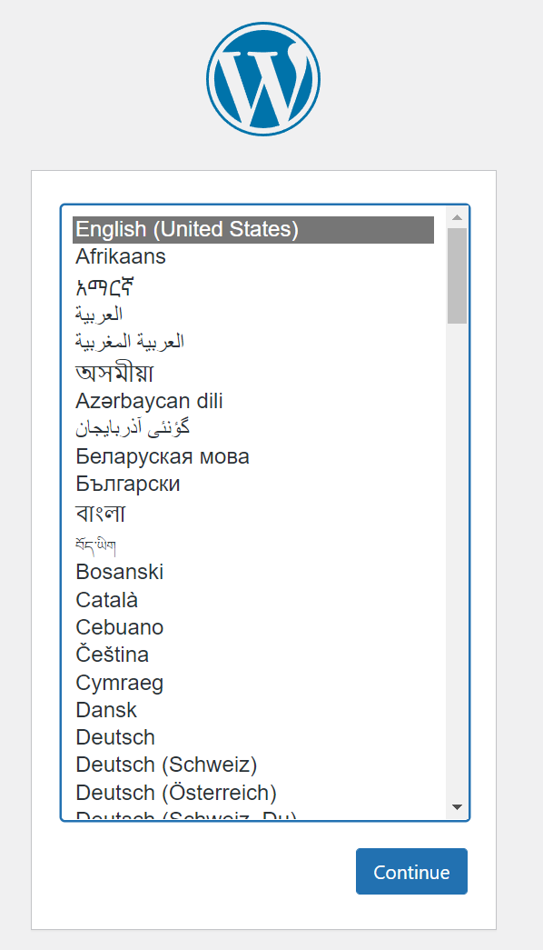
From here on I am going to interact with the device from another computer with a desktop browser. I won’t need to do anything in the device terminal. Using a browser on another computer I navigate to my device’s IP address in the /site folder. The IP address of my device is 192.168.50.216. The complete URL that I use is http://192.168.50.216/site. When I navigate there, I get prompted to select a language.
Word Press Language Prompt
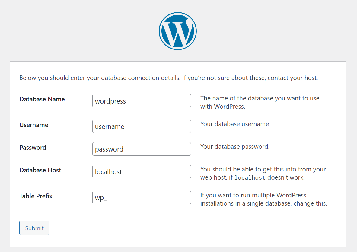
The next page lets you know the information that you will need to complete the setup. That information includes
The database name
The database user name
The database password
The database host
The Table name prefix
The first three items should be familiar. The fourth item, the database host, is the name of the machine that has the database. Since we are running the database and WordPress from the same device this entry will be “localhost”. If we were running more than one site from this device to keep the databases separate, the tables for each instance could have a common prefix. I’m going to use the prefix wp_ for all of the tables. All of this information will be saved to a file named wp-config.php. If you need to change anything later your settings can be modified from that file.
Default WordPress Settings
Enter your database name, user name, and password that you decided earlier. Leave the host name and the table prefix with their defaults and click on “submit.” If you entered everything correctly, on the next screen you will be prompted with a button to run the installation.
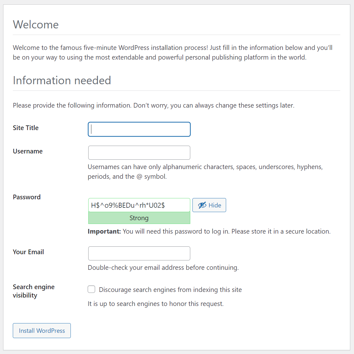
On the next page you must choose some final settings of your Word Press configuration.
Final Setup Screen
After clicking on “Install WordPress” on this screen, you’ve completed the setup. With the instructions as I’ve written them, the site will be in the path /wordpress. The administrative interface will be in the path /wordpress/wp-admin. WordPress is easy to use, but a complete explanation of how it works could be lengthy and won’t be covered here.
Creating a service on a Raspberry Pi or a Jetson is easier than I thought. At the same time, there is still a lot of information to sort through. I’m still exploring the various settings that can be applied to a service. But I wanted to share the information that I thought would be immediately useful. While I was motivated to explore this based on something I was doing on a Jetson Nano, the code and instructions work identically without any need for modification on a Raspberry Pi.
I have a Jetson Mate. The Jetson Mate is an accessory for the Jetson Nano or Jetson Xavier NX Modules. Up to 4 modules can be placed within the Jetson mate to form a cluster. Really the Jetson Mate is just a convenient way to power multiple Jetsons and connect them to a wired network. It contains a 5-port switch so that a single Network cable can be used to connect all of the modules. Despite the Jetsons being in the same box, they don’t have an immediate way to know about each other. Reading the documentation from Seeed Studio, they suggest logging into your router and finding the IP addresses there.
That approach is fine when I’m using the Jetsons from my house; I have complete access to the Network here. But that’s not always possible. On some other networks I may not have access to the router settings. I made a program that would let the Jetson’s announce their presence over UDP Multicast. This could be useful on my Pis also; I run many of them as headless units. I needed for this program to start automatically after the device was powered on and to keep running. How do I do that? By making it a service.
There are several ways that one could schedule a task to run on Linux. I’m using systemd. Systemd was designed to unify service configurations across Linux distributions. The information shown here has applicability well beyond the Pi and Jetson.
The details of how my discovery program works is a discussion for another day. Let’s focus on what is necessary for making a service. For a sample service, let’s make a program that does nothing more than increment a variable and output the new value of the variable. The code that I show here is available on GitHub ( https://github.com/j2inet/sample-service ). But it is small enough to place here also. This is the program.
#include <iostream>
#include <thread>

using namespace std;

int main(int argc, char** argv)
{
    int counter = 0;
    while(true)
    {
        cout << "This is cycle " << ++counter << endl;
        std::this_thread::sleep_for(std::chrono::seconds(10));
    }
}
This program counts, outputting a digit once ever ten seconds. To build the program, you will need to have cmake installed. To install it, use the following command at the terminal.
sudo apt-get install cmake -y
Once that is installed, from the project directory only a couple of commands are needed to compile the program.
cmake ./ make
The program is built, and a new executable named service-sample is now in the folder. If you run it, you will see the program counting. Press CTRL-C to terminate the program. Now we are going to make it into a service.
To make a service, you will need to copy the executable to a specific folder and also provide a file with the settings for the service. For the service settings, I’ve made a file named similarly to the executable. This isn’t a requirement. But it’s something that I’ve chosen to do for easier association. In a file named service-sample.service I’ve place the settings for the service. Many of these settings are technically optional; you only need to set many of them if your specific service is dependent on them. I’m showing more than is necessary for this service because I think some of these settings will be useful to you for other projects and wanted to provide an example.
Here are what some of those settings mean. Note that I also describe some other settings that are not used, but available for you to consider. You can also see documentation for this file in the man pages.
[Unit] section
Documentation viewable with the following command
man systemd.unit
Setting
Meaning
Description
A short text description of the service.
Documentation
URIs at which documentation for the service can be found
Requires
Other units that will be activated or deactivated in conjunction with this unit
Wants
Express weak dependencies. Will try to activate these dependencies first, but if those dependencies fail, this unit will be unaffected
Conflicts
This setting prevents this unit from running at the same time as a conflicting unit
After/Before
Used to express the order in which units are started.These settings contain a space delimited list of unit names.
[Install] Section
Documentation for the [Install] section is viewable at the following URL
Setting
Meaning
RequiredBy / WantedBy
Starts the current service if any of the listed services are started. WantedBy is a weaker dependency than RequiredBy.
Also
Specifies services that are to be started or disabled along with this service
[Service] Section
Documentation for the [Service] section is viewable from the following URL.
man systemd.service
Setting
Meaning
Type
* simple – (default) starts the service immediately * forking – the service is considered started once the process has forked and the parent has exited * oneshot – similar to simple. Assumes service does its job and exits. * notify – considers a service started when it sends a signal to systemd
ExecStart
Commands with arguments to execute to start the service. Note that when Type=oneshot that multiple commands can be listed and executed sequentially.
ExecStop
Commands to execute to stop the service
ExecReload
Commands to execute to trigger a configuration reload of the service
Restart
When this option is enabled, the service will be restarted when the service process exits or is killed
RemainAfterExit
When True, the service is considered active even after all of its processes have exited. Mostly used with Type=oneshot.
Deploying
Having the executable and this service file are not themselves enough. They must also be moved to an appropriate location and the service must be activated. I’ve placed the steps for doing this in a script. This script is intentionally a bit verbose to make it clear what the script is doing at any time. The first thing that this script does is terminate the service. While this might sound odd given that we haven’t installed the service yet, I do this to make the script rerunnable. If this is not the first time that the script has run, it is possible that the service process is running. To be safe, I terminate it.
Next, I copy files to their appropriate locations. For this simple service those files are one executable binary and the service settings. The executable is placed in /usr/local/bin. The service settings are copied to /etc/systemd/system/. On the service settings, the permissions on it are changed with chmod. This will ensure the owner has read/write permissions and the group has read permissions.
With the files for the service in place, we next ask systemd to reload the service definitions. I then probe the status for my service. While my service isn’t running, I should see it listed. I then enable the service (so that it will run on system startup) and then start the service (so that I don’t need to reboot to see it running now) and then probe the system status again.
echo "stopping service. Note that the service might not exists yet."
sudo systemctl stop service-sample

echo "--copying files to destination--"
sudo cp ./service-sample /usr/local/bin
sudo cp ./service-sample.service /etc/systemd/system/service-sample.service
echo "--setting permissiongs on file--"
sudo chmod 640 /etc/systemd/system/service-sample.service
echo "--reloading daemon and service definitions--"
sudo systemctl daemon-reload
echo "--probing service status--"
sudo systemctl status service-sample
echo "--enabling service--"
sudo systemctl enable service-sample
echo "--starting service service status--"
sudo systemctl start service-sample
echo "--probing service status--"
sudo systemctl status service-sample
After the service is installed and running, you can use the command for probing the status to see what it is up too. The last few lines that the service has outputted will display with the service information. Probe the service status at any time using this command.
sudo systemctl status service-sample
Sample output from the command follows.
pi@raspberrypi:~ $ sudo systemctl status service-sample
● service-sample.service - Counting service.
   Loaded: loaded (/etc/systemd/system/service-sample.service; enabled; vendor preset: enabled)
   Active: active (running) since Wed 2022-03-09 15:57:12 HST; 12min ago
 Main PID: 389 (service-sample)
    Tasks: 1 (limit: 4915)
   CGroup: /system.slice/service-sample.service
           └─389 /usr/local/bin/service-sample

Mar 09 16:09:29 raspberrypi service-sample[389]: This is cycle 361
Mar 09 16:09:31 raspberrypi service-sample[389]: This is cycle 362
Mar 09 16:09:33 raspberrypi service-sample[389]: This is cycle 363
Mar 09 16:09:35 raspberrypi service-sample[389]: This is cycle 364
Mar 09 16:09:37 raspberrypi service-sample[389]: This is cycle 365
Mar 09 16:09:39 raspberrypi service-sample[389]: This is cycle 366
Mar 09 16:09:41 raspberrypi service-sample[389]: This is cycle 367
Mar 09 16:09:43 raspberrypi service-sample[389]: This is cycle 368
Mar 09 16:09:45 raspberrypi service-sample[389]: This is cycle 369
Mar 09 16:09:47 raspberrypi service-sample[389]: This is cycle 370
pi@raspberrypi:~ $
Screenshot of service output. Note the green dot indicates the service is running.
The real test for the service comes after reboot. Once you have the service installed and running on your Jetson or your Pi, reboot it. After it boots up, probe the status again. If you see output, then congratulations, your service is running! Now that a service can be easily created and registered, I’m going to refine the code that I used for discovery of the Pis and Jetsons for another post.
Posts may contain products with affiliate links. When you make purchases using these links, we receive a small commission at no extra cost to you. Thank you for your support.
Android supports a number of different text input types. If you create a text field in which someone is intended to enter a phone number, address, email address, you can set the text input type on the text field to have the keyboard automatically restrict what characters it presents to the user.
<EditText android:inputType="phone" />
I was working on something for which I needed to ensure that the user selected an emoji. Unfortunately, there’s not an input type to restrict a user to emoji. How do I ensure taht the user can only enter emoji? I could implement my own keyboard that only displays emoji, but for the time being I do not what to implement such a thing for the application that I’m building. There are a number of different possible solutions for this. The one I chose was to make a custom text input field and an InputFilter for it.
Making a custom field may sound like a lot of work, but it isn’t. The custom field itself is primary declarations with only a single line of initialization code that applies the filter. The real work is done in the filter itself. For a custom InputFilter, make a class that derives from InputFilter. There is a single method on the class to define named filter.
The filter method receives the text sequence that is going to be assigned to the text field. If we want to allow the field value to be assigned to the text field, the function can return null. If there is a character of which I don’t approve, I’ll return an empty string which will clear the text field. If I wanted to replace a character, I could return a string in which I had performed the replacement. The value returned by this function will be applied to the text field.
In my implementation for this function, I step through each character in the string (passed as a CharSequence, a String is a type of CharSequence) and check the class of each character. If the character is not of acceptable class, then I return an empty string to clear the text field. For your purposes, you may want to strip characters out and return the resulting string.
The function Character::getType will return the character type or class. To ensure that the character is an emoji, I check to see if the type value equals to Character::SURROGATE or Character::OTHER_SYMBOL.
private class EmojiFilter : InputFilter {

    override fun filter(
        source: CharSequence?,
        start: Int,
        end: Int,
        dest: Spanned?,
        dstart: Int,
        dend: Int
    ): CharSequence? {
        for( i in start .. end-1) {
            var type = Character.getType(source!!.get(i)).toByte()
            if(type != Character.SURROGATE && type != Character.OTHER_SYMBOL) {
                return "xx";
            }
        }
        return null;
    }
}
Now that the filter class is defined, I can create my custom text field. It has next to no code within it.
And that’s it. While Android doesn’t give the option of showing only the Emoji characters, with this in place I’m assured that a user will only be able to enter Emoji characters.
I recently worked on a project that made use of Phidgets hardware. Phidgets has many offers for interfacing hardware sensors to a computer using USB. Provided that the drive is installed, using the service is pretty straight forward. They have software components available for a variety of languages and operating systems. For the project that I was working on, a computer would have multiple Phidget RFID readers. When there are multiple instances of hardware on a system, a specific instance can be addressed through it’s serial number. On this project, the serial numbers were stored in a configuration file. For the single machine on which this project was deployed, that was fine. Once that was a success the client wanted the software deployed to another 7 machines.
The most direct strategy for this would be to make a configuration file for each machine that had its specific serial numbers in it. I did this temporarily, but I am not a fan of having differences in deployment files. A simple mistake could result in the wrong configuration being deployed and a non-working software system. Deployments would be frequent because users were interacting with the software during this phase of development. An unexpected problem we encountered was someone disconnected hardware from one computer and moved it to another. Why they decided to perform this hardware swap is not known to me. But it resulted in two machines sensors that were no longer responsive.
After a little digging I found a much better solution.
For some reason the Phidgets code examples that I encounter don’t mention this, but it is also possible to get notification of a Phidgets device being connected or disconnected from the computer and the serial number of the device being references. I used a .Net environment for my development, but this concept is applicable in other languages too. I’ll be using .Net in my code examples.
In the .Net environment, Phidget’s offers a class named Manager in their SDK. The Manager class when instantiated raises Attached and Detached events each time an item of hardware is connected or disconnected from the system. If the class is instantiated after hardware has already been connected, it will raise Attached events for each item of hardware that is already there. The event argument object contains a member of the class Phidget that among other data contains the serial number of the item found and what type of hardware it is. For the application I was asked to update, I was only interested in the RFID reader hardware. I had the code ignore any Phidget of any other type. While it is unlikely the client would randomly connect such hardware to the machines running the solution, for the sake of code reuse it is better to have such protection in the application.
Let’s make an application that will list the RFID readers and the RFID readers detected by each tag. I’m writing this in WPF. Not shown here is some of the typical code you might find in such a project such as a ViewModel base class. In my sample project, I wrapped the Phidgets Manager class in another class that will also keep a list of the Phidget object instances that it has found. An abbreviated version of the class follows. The Phidget’s Manager class will start raising Attached and Detached events once its Open() method has been called. If there is already hardware attached, expect events to be raised immediately.
    public partial class PhidgetsManager:IDisposable
    {
        Manager _manager;
        List<Phidget> _phidgetList = new List<Phidget>();
        public PhidgetsManager()
        {
            _manager = new Manager();
            _manager.Attach += _manager_Attach;
            _manager.Detach += _manager_Detach;
        }

        private void _manager_Detach(object sender, Phidget22.Events.ManagerDetachEventArgs e)
        {
            _phidgetList.Remove(e.Channel);
            OnPhidgetDetached(e.Channel);
        }

        private void _manager_Attach(object sender, Phidget22.Events.ManagerAttachEventArgs e)
        {
            _phidgetList.Add(e.Channel);
            OnPhidgetAttached(e.Channel);
        }
        public enum Action
        {
            Connected,
            Disconnected
        }

        public class PhidgetsActionEventArgs
        {
            public Phidget Phidget { get; internal set;  }
            public Action Action { get; internal set; }
        }

        public delegate void PhidgetsActionEvent(object sender, PhidgetsActionEventArgs args);
        public event PhidgetsActionEvent DeviceAttached;
        public event PhidgetsActionEvent DeviceDetached;

        protected void OnPhidgetAttached(Phidget p)
        {
            if (DeviceAttached != null)
            {
                var arg = new PhidgetsActionEventArgs()
                {
                    Action = Action.Connected,
                    Phidget = p
                };
                DeviceAttached(this, arg);
            }
        }

        protected void OnPhidgetDetached(Phidget p)
        {
            if (DeviceDetached != null)
            {
                var arg = new PhidgetsActionEventArgs()
                {
                    Action = Action.Connected,
                    Phidget = p
                };
                DeviceDetached(this, arg);
            }
        }

    }
In my MainViewModel I only wanted to capture the RFID readers. It has its own list for maintaining these. When a device of the right type is found, I create anew RFID number and assign its DeviceSerialNumber. When the class’s Open() method is called, it will attach to the correct hardware since the serial number has been set. The RFID instance is added to my list. My list uses a wrapper class that exposes the device serial number and the current RFID tag that the device sees. This is exposed through a ViewModel object so that the UI will automatically update.
    public class RFIDReaderViewModel: ViewModelBase, IDisposable
    {
        RFID _reader;

        public RFIDReaderViewModel(Phidget phidget)
        {
            if(phidget == null)
            {
                throw new ArgumentNullException("phidget");
            }
            if(phidget.ChannelClass != ChannelClass.RFID)
            {
                throw new ArgumentException($"Phidget must be an RFID Reader. The received item was a {phidget.ChannelClassName}");
            }
            this.Reader = new RFID();
            this.Reader.DeviceSerialNumber = phidget.DeviceSerialNumber;
            this.Reader.Tag += Reader_Tag;
            this.Reader.TagLost += Reader_TagLost;
            this.Reader.Open();
        }

        private void Reader_TagLost(object sender, Phidget22.Events.RFIDTagLostEventArgs e)
        {
            Dispatcher.CurrentDispatcher.Invoke(() =>
            {
                CurrentTag = String.Empty;
            });
        }

        private void Reader_Tag(object sender, Phidget22.Events.RFIDTagEventArgs e)
        {
            Dispatcher.CurrentDispatcher.Invoke(() =>
            {
                CurrentTag = e.Tag;
            });
        }

        public RFID Reader
        {
            get { return _reader;  }
            set { SetValueIfChanged(() => Reader, () => _reader, value); }
        }
        String _currentTag;
        public String CurrentTag
        {
            get { return _currentTag;  }
            set { SetValueIfChanged(() => CurrentTag, ()=>_currentTag, value);  }
        }

        public void Dispose()
        {
            try
            {
                this.Reader.Close();
            }
            catch (Exception exc)
            {

            }
        }
    }
All that’s left is the XAML. In the XAML for now, I’m only interested in listing the serial numbers and the tag strings.
With that in place, now when I run the project, I get live updates of RFID tags coming into or out of range of each of the readers connected.
If you try to run this though, you may encounter a problem. The RFID readers (as the name implies) use radio frequencies for their operation. If they are close to each other, they may interact and interfere with each other. Don’t worry, this doesn’t mean that you can’t use them in close proximity. In my next entry I’ll show how to deal with RFID readers that are close to each other and mitigate interference through software.
I’m working on an application that uses Android’s WiFi P2P functionality so that two phones can communicate directly with each other. Because of the nature of this application, I need to have two instances of this program running at once. The only problem is that Android Studio only let’s me have one debug target at a time. I thought of a few potential solutions.
* Deploy to one phone, start the application, then start debugging on the second
* Use a second computer and have each phone connected to a computer
Both of these solutions have shortcomings. They are both rather cumbersome. While this isn’t a supported scenario yet, there’s a better solution. We can use two instances of Android Studio on the same computer to open the project. We need a little bit of support from the operating system to pull this off. Android will otherwise see that we are opening a project that is already open otherwise. Before doing this, we need to make a symbolic link to our project.
A symbolic link is an entry in the file system that has its own unique path but points to existing data on the file system. Using symbolic links, a single file could be accessed through multiple paths. To Android Studio, these are two separate projects. But since it is the same data streams on the file system, the two “instances” will always be in sync. There are some files are are going to be unique to one instance or the other, but we will cover that in a
Symbolic links are supported on Windows, macOS, and on Linux. To make a symbolic link on macOS, use the ln command.
ln -s /original/path /new/linked/path
On Windows, use the mklink command.
mklink /j c:\original\path c:\linked\path
Make sure that Android Studio is closed. Make a copy of your project’s folder. In the new copy that you just made, you are going to erase most of the files. Delete the folder app/src in the copy. Open a terminal and navigate to the root of the copied project. In my case the original project is called P2PTest and the other is called P2PCopy. To make the symbolic link for the src file I use the following command.
ln -s ../P2PTest/app/src app/src
Some other resources that I’ve looked at suggest doing the same thing for the the project’s build.gradle and the build.gradle for each module. For simple projects, the only module is the app. I tried this and while it worked fine for the project’s build.gradle, I would always get errors about a broken symbolic link when I tried with the build.gradle at the module level. In the end, I only did this for the project level.
## ln -s ../P2PTest/app/build.gradle app/build.gradle ## this line had failed results
ln -s ../P2PTest/build.gradle build.gradle
Because I could not make changes to the module’s build.gradle, if there are changes made to it then it will need to be copied between the instances of the project. Thankfully, most changes to a project will be in the source files. While it is possible to edit the source files from eithe project, I encourage only editing from the primary project. This will help avoid situations where you have unsaved changes to the same file in different editors and have to manually merge them.
When you are ready to debug, you can set one instance of Android Studio to one of your phones, and the other instance to the other phone. Here, I have two instances set to deploy to a Galaxy Note 5 and a Galaxy Note 8.
I’m back from a recent trip out of the country. While the facility I was staying at would have an Internet connection, the price for Internet access for about a week was a little over 100 USD. I’d rather go without a connection. While I didn’t have access to the Internet, I did have access to a local network. I considered options on how to bring media with me. Rather than bring a few movies and songs here and there I wanted to indiscriminately copy what I could to a drive. In addition to myself, there were three other people with me that might also want to view the media. It made since to host the media on a pocket-sized web server. I setup a Raspberry Pi to do just this and took it with me on the trip.
After the trip was over, I thought to myself that there should be a way to do the same thing in a more compact package. I started to look at what the smallest Raspberry Pi Computer Module based setup would look like, and as I mentally constructed a solution in my mind, I realized it was converging to the same form factor as a phone. I’ve got plenty of old phones lying about. While I wouldn’t suggest this as a general solution (phones are a lot more expensive than a Pi) it is what I decided to have fun with.
Extra, unused Android devices.
There are various ways to run NodeJS on a phone and some other apps in the app store that let you host a web server on your phone. I didn’t use any of these. I am reinventing the wheel simply because I find enjoyment in creating. It was a Sunday night, I was watching my TV lineup, and decided to make a simple proof of concept. I only wanted the PoC to listen for incoming request and send a hard coded HTML page back to the client. I had that working in no time! I’ll build upon this to give it the ability to host static files and media files when I do a future update on this. I’m taking a moment to talk about how I build this first.
I created a new Android project. Before writing code, I declared a few permissions. I like to do this first so that later on I don’t have to wonder why a specific call failed. The permissions I added are for Internet access, accessing the WiFi state, and access to the Wake Lock to keep the device from completely suspending. For what I show here, only Internet capabilities are going to be used. You can choose to omit the other two permissions for this version of the program.
With the permissions in place, I started writing the code. There are only three classes used in the web server (counting an interface as a class).
WebServer – Listens for incoming request and passes them off to be handled as they com in
ClientSocketHandler – Processes an incoming class and gives the response
IStatusUpdater – used for passing status information back to the UI
The WebServer class accepts in its constructor the port on which it should run and a Context object, which is needed for some other calls. A WebServer instance does not begin to listen for connections until the start() method is called. Once it is started, the device retrieves the address of the WiFi adapter and creates a socket that is bound to this address. A status message is also sent to the UI so that it can show the device’s IP address. The class then creates the thread that will listen for incoming connections.
In the function listenerThread(), the class waits for an incoming connection. As soon as it receives one, it creates a new ClientSocketHandler with the socket and lets the ClientSocketHandler process the request and immediately goes back to listening for another connection. It doesn’t wait for the ClientSocketHandler to finish before waiting for the next connection.
package net.j2i.webserver.Service
import android.content.Context
import android.net.wifi.WifiManager
import android.text.format.Formatter
import java.net.InetSocketAddress
import java.net.ServerSocket
import java.net.Socket
import kotlin.concurrent.thread
class WebServer {
    companion object {
    }
    val port:Int;
    lateinit var receiveThread:Thread
    lateinit var  listenerSocket:ServerSocket;
    var keepRunning = true;
    val context:Context;
    var statusReceiver:IStatusUpdateReceiver
    constructor(port:Int, context: Context) {
        this.port = port;
        this.context = context;
        this.statusReceiver = object : IStatusUpdateReceiver {
            override fun updateStatus(ipAddress: String, clientCount: Int) {
                fun updateStatus(ipAddress: String, clientCount: Int) {
                }
            }
        }
    }
    fun start() {
        keepRunning = true;
        val wifiManager:WifiManager =
            this.context.getSystemService(Context.WIFI_SERVICE) as WifiManager;
        val wifiIpAddress:String = Formatter.formatIpAddress(wifiManager.connectionInfo.ipAddress);
        this.statusReceiver.updateStatus(wifiIpAddress, 0)
        this.listenerSocket = ServerSocket();
        this.listenerSocket.reuseAddress = true;
        this.listenerSocket.bind(InetSocketAddress(wifiIpAddress, this.port))
        this.receiveThread = thread(start = true) {
                this.listenerThread()
        }
        //this.receiveThread.start()
    }
    fun listenerThread() {
        while(keepRunning) {
            var clientSocket: Socket = this.listenerSocket.accept()
            val clientSocketHandler = ClientSocketHandler(clientSocket)
            clientSocketHandler.respondAsync()
        }
    }
}
In ClientSocketHandler, the class grabs the input stream (to read the request from the remote client) and the OutputStream (to send data back to the client). Now I haven’t implemented the HTTP protocol. But in HTTP, the client will send a one or more lines that make up the request followed by a blank line. For now, my client handler reads from input stream until that blank line is encountered. Once received, it composes a response.
I’ve got the HTML string that the client is going to return hardcoded into the application. In the response string is converted to a byte array. The size of this array is needed for one of the response headers. The client will receive the size of the response in the header Content-Length. The header for the response is constructed as a string and converted to a byte array. Then the two arrays are sent back to the client (first the header, then the content). After the response is sent, the client has done its work.
package net.j2i.webserver.Service
import android.util.Log
import java.lang.StringBuilder
import java.net.Socket
import kotlin.concurrent.thread
class ClientSocketHandler {
    companion object {
        val TAG = "ClientSocketHandler"
    }
    private val clientSocket: Socket;
    private val responseThread:Thread
    constructor(sourceClientSocket:Socket) {
        this.clientSocket = sourceClientSocket;
        this.responseThread = thread( start = false) {
                this.respond()
        }
    }
    public fun respondAsync() {
        this.responseThread.run()
    }
    private fun respond() {
        val inputStream = this.clientSocket.getInputStream()
        val outputStream = this.clientSocket.getOutputStream()
        var requestReceived = false;
        while(inputStream.available()>0 &&  !requestReceived) {
            val requestLine = inputStream.bufferedReader().readLine()
            Log.i(ClientSocketHandler.TAG, requestLine)
            if(processRequestLine(requestLine)) {
            requestReceived = true;}
        }
        val sb:StringBuilder = StringBuilder()
        val sbHeader = StringBuilder()
        sb.appendLine(
            "<html>"+
                    "<head><title>Test</title></head>" +
                    "<body>Test Response;lkj;ljkojiojioijoij</body>"+
                   "</html>")
        sb.appendLine()
        val responseString = sb.toString()
        val responseBytes = responseString.toByteArray(Charsets.UTF_8)
        val responseSize = responseBytes.size
        sbHeader.appendLine("HTTP/1.1 200 OK");
        sbHeader.appendLine("Content-Type: text/html");
        sbHeader.append("Content-Length: ")
        sbHeader.appendLine(responseSize)
        sbHeader.appendLine()
        val responseHeaderString = sbHeader.toString()
        val responseHeaderBytes = responseHeaderString.toByteArray(Charsets.UTF_8)
        outputStream.write(responseHeaderBytes)
        outputStream.write(responseBytes)
        outputStream.flush()
        outputStream.close()
    }
    fun processRequestLine(requestLine:String): Boolean {
        if(requestLine == "") {
            return true;
        }
        return false;
    }
}
The interface that I mentioned, IStatusUpdateReceiver, is currently only being used to communicate the IP address on which the server is listening back to the UI.
package net.j2i.webserver.Service
interface IStatusUpdateReceiver {
    fun updateStatus(ipAddress:String, clientCount:Int);
}
Since the server runs on a different thread, before updating the UI I must make sure that UI related calls are being performed on the main thread. If you look in the class for MainActivity you will see that I created the WebServer instance in the activity. I’m only doing this because it is a PoF. If you make your own application, implement this as a service. I set the statusReceiver member of the WebServer to an annonymous class instance that does nothing more than update the IP address displayed in the UI. The call to set the text in the UI is wrapped in a runOnUiThread block. After this is setup, I call start() on the webserver to get things going.
I was happy that my proof of concept worked. I haven’t yet decided if I am going to throw this away or continue working from this. In either case, there are a few things that I want to have in whatever my next version is. I do absolutely no exception handling or cleanup in this code. It needs to be able to timeout a connection and refuse connections if it gets inundated. I also want my next version to do actual processing of the incoming HTTP request and serve up content that has been saved to the device’s memory, such as a folder on the device’s memory card. While I am making this to serve up static content, I might add a few services to the server/device side, such as a socket server. That will require a lot more thought.