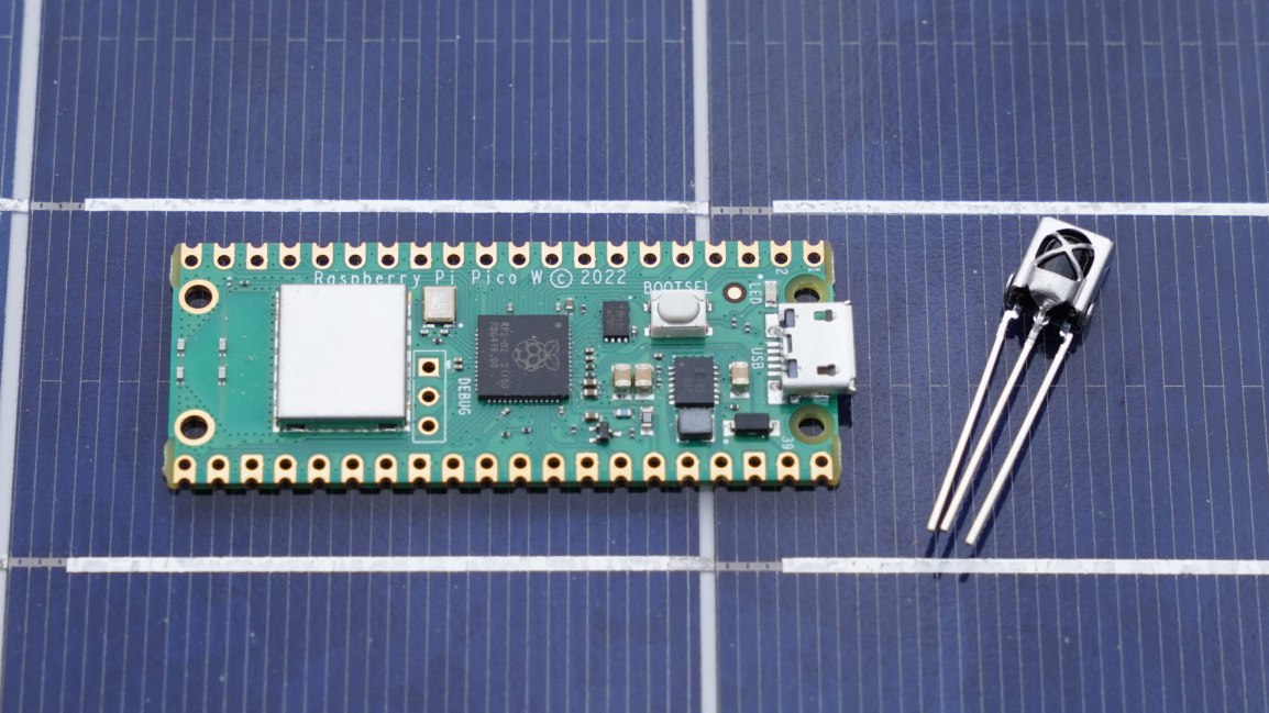
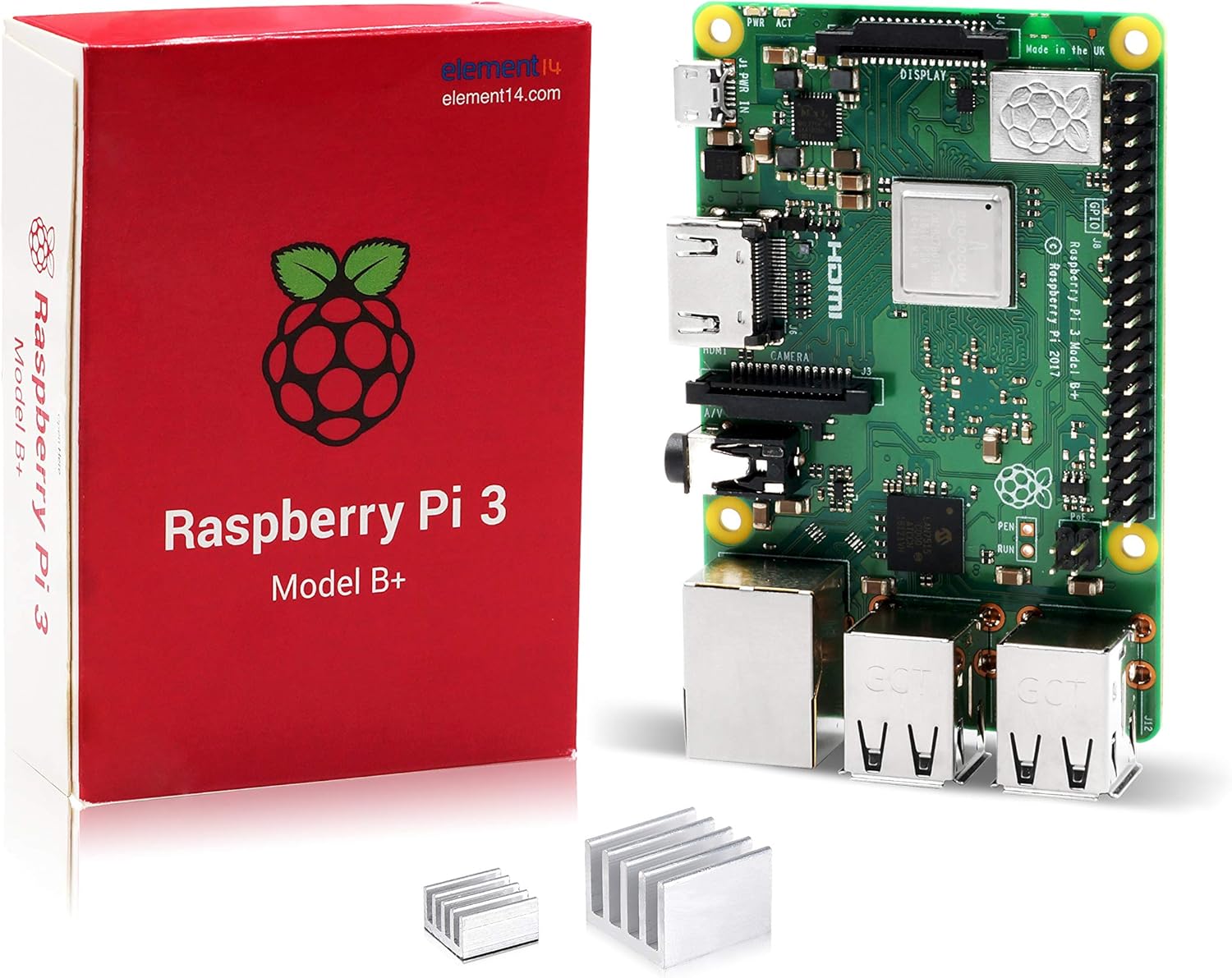
In a previous post, I mentioned that I was re-introducing myself to development for the Pi Pico. The Pico is a microcontroller, often compared to an Arduino, that can be programmed from a Linux, Mac, or Windows machine. The Pico is based on the RP2040 chip. This is an ARM based Cortex-M0 dual core processor, generally running between 125 and 133 MHz. It has 264 KB of SRAM, 2 MB of flash memory, 26 general purpose IO pins, some of which support additional functionality. The other functionality overlaid on these pins includes
- 2 UART pins
- 2 SPI controllers
- 2 I2C controllers
- 16 PWM channels
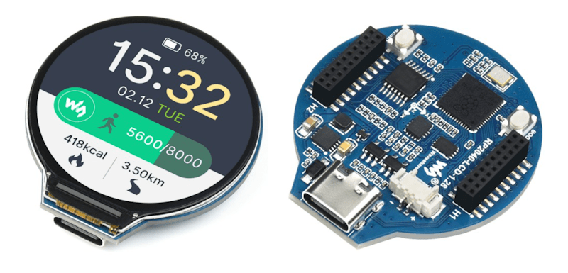
There are several development boards that use the RP2040. Collectively, I generically refer to all of these as Pico. It is a bit easier to say then “RP2040 based board.”

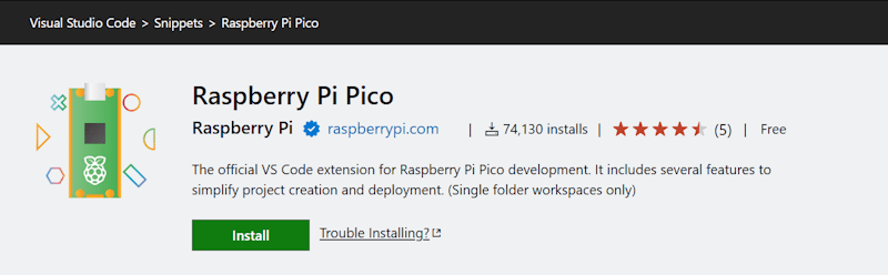
I already had a few machines setup for development for the Raspberry Pi Pico. While that procedure still works, as do those development machines, I was recently reintroducing myself to Pico development. I started with a clean installation and went to the currently published instructions for setup. The more recent instructions are a lot easier to follow; there are less dependencies on manually setting paths and downloading files. The easier process is made possible through a Visual Studio Code plugin. This extension, which is still labeled as a zero version at the time that I am making this post (0.17.3) adds project generation and sample code along with scripts and automations for common tasks. To get started, just Install the Raspberry Pi Pico Visual Studio Code Extension. Once it is installed, you’ll have a new icon on the left pane of VS Code for Pico related tasks.
The first time you do anything with this icon, expect it to be slow. It installs the other build tools that it needs on-demand. I prefer to use the C++ build tools. Most of what I write here will be focused on that. I’ll start with creating a new C++ project. Double-clicking on “New C/C++ Project” from the Pico tools panel gets the process started.

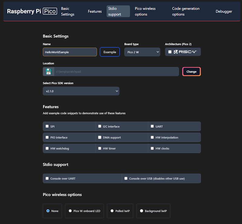
This will only be a “Hello World” program. We will have the Pico print a message to a serial port in a loop. The new project window lets us specify our target hardware, including which hardware features that we plan to use. Selecting a feature will result in the build file for the project linking to necessary libraries for that feature and adding a small code sample that access that feature. Select a folder in which the project folder will be created, enter a project name, and check the box labeled “Console over USB.” After selecting these options, click on the “Create” button.
This is the part that takes a while the first time. A notification will show in VS Code stating that it is installing the SDK and generating the project. The wait is only a few minutes. While this is executing, it is a good time to grab a cup of coffee.

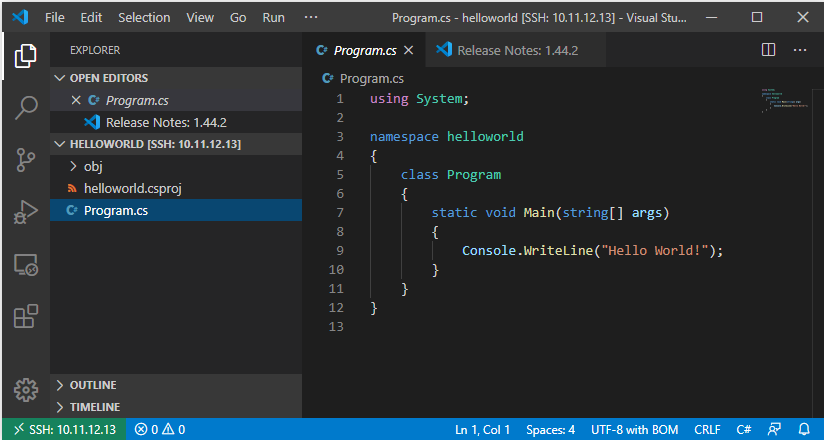
When you get back, you’ll see VS Code welcome you with a new project. The default new project prints “Hello, world!\n” in a loop with a 1 second delay. Grab your USB cable and a Pico. We can immediately start running this program to see if the build chain works. On the Pico, there’s a button. Connect your USB cable to your computer, then connect the Pico, making sure you are holding down this button as you connect it. The Pico will show up on your computer as a writable drive. After you’ve done this, take note of which serial ports show up on your computer. In my case, I’m using Windows, which shows that Com1 is the only serial port. In VS Code, you now have several tasks for your project that you can execute. Double-click on Run Project (USB). The code will compile, deploy to the Pico, and the Pico will reboot and start running the code.

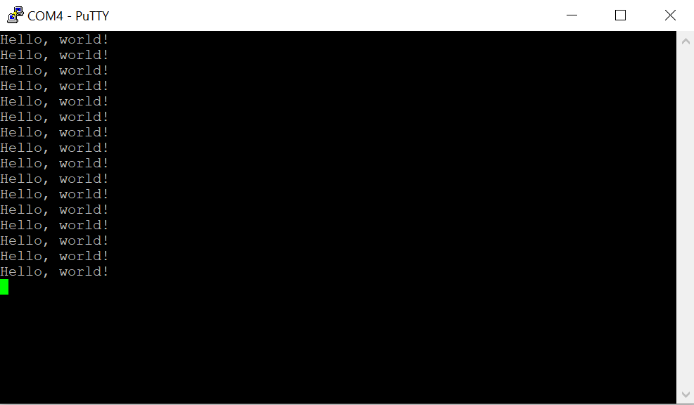
Check to see what serial ports exist on your computer now. For me, there is a new port named Com4. Using PuTTY, I open Com4 at a baud rate of 115,200. The printed text starts to show there.
Using the USB UART for output is generally convenient, but at time you may want to use the USB for other features. The USB output is enabled or disabled in part through a couple of lines in the CMakeList.txt file.
pico_enable_stdio_uart(HelloWorldSample 0)
pico_enable_stdio_usb(HelloWorldSample 1)
The 1 and 0 can be interpreted as meaning enable and disable. Swap these values and run the project again by disconnecting the Pico, reattach while pressing the button, and then selecting the Run Project (USB) option from VS Code. When you run the code this time, the output is being transmitted over GPIO pins 0 and 1. But how do we read this?
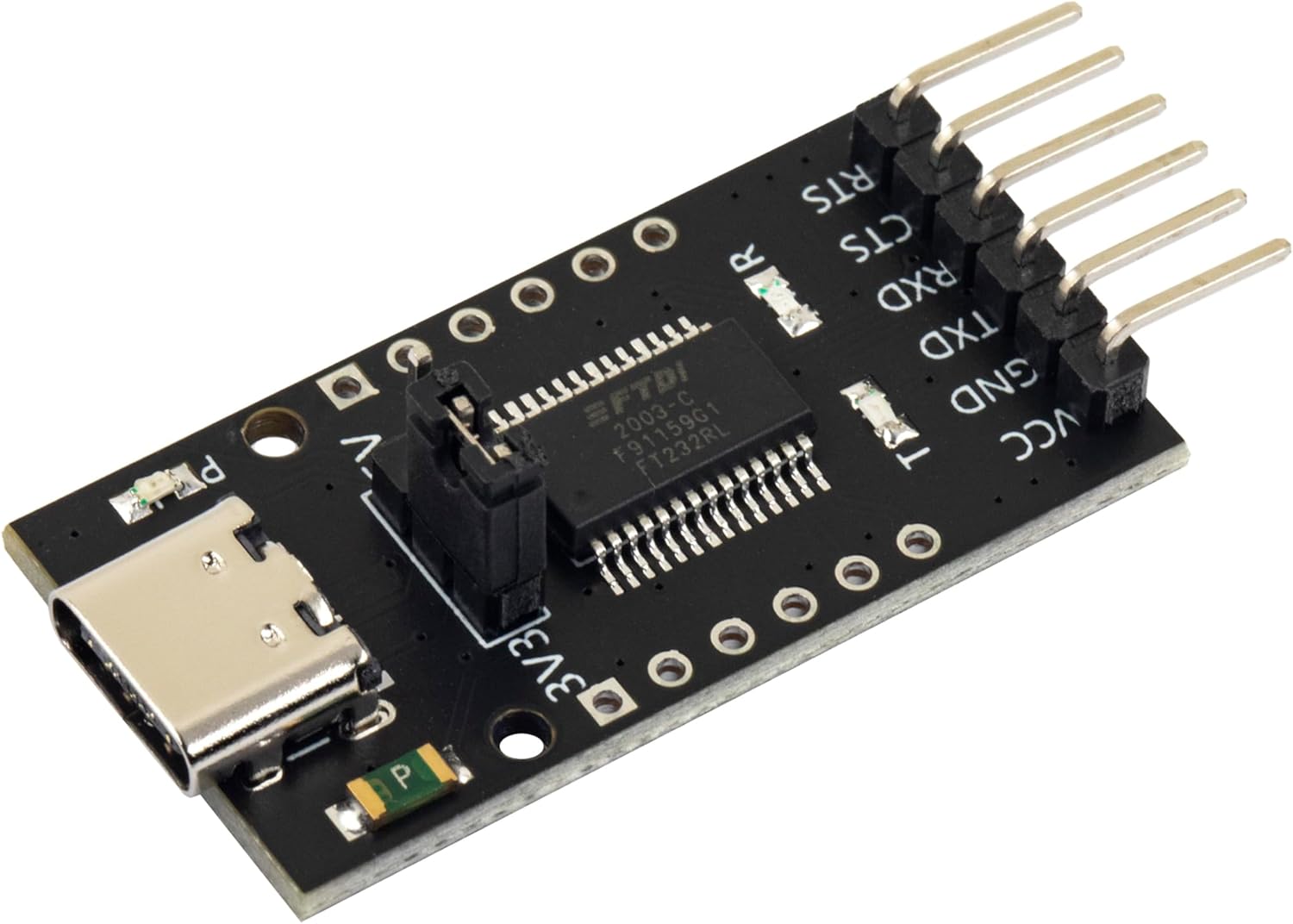
FTDI USB
FTDI is the name of an integrated circuit manufacturer. For microcontroller interfacing, you might often see people refer to “FTDI USB” cables. These are USB devices that have 3 or 4 pins for connecting to other serial devices. These are generally cheaply available. The pins that we care about will be labeled GND (Ground), TX (Transmit), and RX (Receive). The transmit pin on one end of a serial exchange connects to the receive end on the other, and vice versa. On the Pico, the default pins used for uart0 (the name of our serial port) are GP0 for TX and GP1 for RX. When connecting an FTDI device, connect the FTDI’s RX to the Pico’s TX on GPO, then the FTDI’s TX to the Pico’s RX (on GP1), and finally the FTDI’s ground to the Pico’s ground.
GPIO – Setting a Pin
Many, Pico’s have a LED attached to one of the pins that is immediately available for test programs. While many do, not all do. On the Pi Pico and Pi Pico 2, GPIO 25 is connected to a LED. On the Pi Pico W, the LED is connected to the WiFi radio and not the RP2040 directly. For uniformity, I’ll drive an external LED. I’ve taken a LED and have it connected in series with a resistor. 220Ω should be a sufficient value for the resistor. I’m connecting the longer wire of the LED to GP5 and the shorter pin to ground.
In the code, the pin number is assigned to a #define. This is common, as it makes the code more flexible for others that may be using a different pin assignment. Before we can start writing to the pin, we need to gall an initialize function for the pin number named gpio_init(). After the initialization, we need to set the pin to be either in input or output mode. Since we are going to be controlling a LED, this needs to be output mode. This is done with a call to gpio_set_dir() (meaning “set direction”) passing the pin number as the first argument, and the direct (GPIO_IN or GPIO_OUT) as the second argument. For writing, we use GPIO_OUT. With the pin set to output, we can drive the pin to a high or low state by calling gpio_put(). The pin number is passed in the first argument, and a value indicating whether it should be in a high or low state in the second argument. A zero value is considered low, while a non-zero value is considered high. To make it apparent that the LED is being driven by our control of the pin (and not that we just happened to wire the LED to a pin that is always high) we will turn the light on and off once per second. In a loop, we will turn the light on, wait half a second, turn the light off, and wait again.
#include <stdio.h>
#include "pico/stdlib.h"

#define LED_PIN 5
int main()
{
    stdio_init_all();
    gpio_init(LED_PIN);
    gpio_set_dir(LED_PIN, GPIO_OUT);

    while (true) {
        gpio_put(LED_PIN, 1);
        sleep_ms(500);
        gpio_put(LED_PIN, 0);
        sleep_ms(500);
    }
}
When we run the code now, we should see the light blink.
Up Next: Programmable IO – The Processor within the Processor
While the GPIO system can be manipulated by the main processor core, there are also smaller processors on the silicon that exist just for controlling the GPIO. These processors have a much smaller reduced set but are great for writing deterministic code that controls the pins. This system of sub-processors and the pins that they control are known as “Programmable IO.” They are programmed using assembler. There’s much to say about PIO. In the next post that I make on the Pico, I’ll walk you through an introduction to the PIO system.
Posts may contain products with affiliate links. When you make purchases using these links, we receive a small commission at no extra cost to you. Thank you for your support.
Mastodon: @j2inet@masto.ai
Instagram: @j2inet
Facebook: @j2inet
YouTube: @j2inet
Telegram: j2inet
Bluesky: @j2i.net


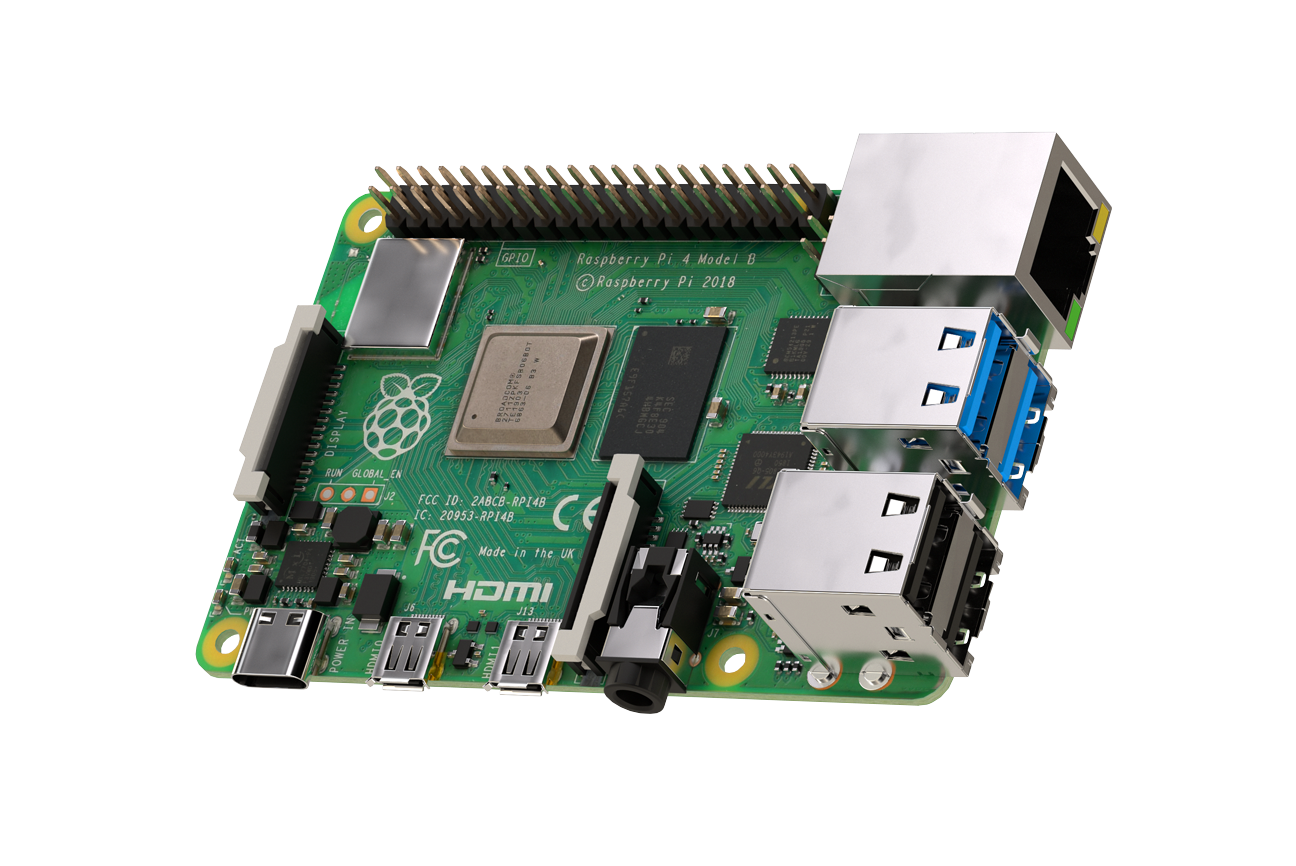
 Raspberry Pi 4