SSDP Discovery in HTML

While implementing a few projects I decided to implement them in HTML since it would work on the broadest range of my devices of interest. My projects of interest needed to discover additional devices that are connected to my home network. I used
SSDP for discovery.

SSDPDiscovery

SSDP (Simple Service Discover Protocol ) is a UDP based protocol that is a part of UPnP for finding other devices and services on a network. It’s implemented by a number of devices including network attached storage devices, Smart TVs, and home automation systems. There are a lot of these devices that expose functionality through JSON calls. You can easily make interfaces to control these devices. However, since the standards for HTML and JavaScript don’t include a UDP interface, how to perform discovery isn’t immediately obvious. Alternatives to SSDP include having the user manually enter the IP address of the device of interest or scanning the network. The latter of those options can raise some security flags when performed on some corporate networks.

For the most part, the solution to this is platform dependent. There are various HTML based solutions that do allow you to communicate over UDP. For example, the BrightSign HTML5 Players support UDP through the use of roDatagramSocket. Chrome makes UDP communication available through chrome.udp.sockets. Web pages don’t have access to this interface (for good reason, as there is otherwise potential for this to be abused). Although web apps don’t have access, Chrome extensions do. Chrome Extensions won’t work in other browsers. But at the time of this writing Chrome accounts for 67% of the browser market share and Microsoft has announced that they will use Chromium as the foundation for their Edge browser. While this UDP socket implementation isn’t available in a wide range of browsers, it is largely available to a wide range of users since this is the browser of choice for most desktop users.

To run HTML code as an extension there are two additional elements that are needed: a manifest and a background script. The background script will create a window and load the starting HTML into it.

chrome.app.runtime.onLaunched.addListener(function() {
    chrome.app.window.create('index.html', {
        'outerBounds': {
        'width': 600,
        'height': 800
        }
    });
});

I won’t go into a lot of detail about what is in the manifest, but I will highlight its most important elements. The manifest is in JSON format. The initial scripts to be run are defined app.background.scripts. Other important elements are the permission element, without which the attempts to communicate over UDP or join a multicast group will fail and the manifest_version element. The other elements are intuitive.

        {
            "name": "SSDP Browser",
            "version": "0.1",
            "manifest_version": 2,
            "minimum_chrome_version": "27",
            "description": "Discovers SSDP devices on the network",
            "app": {
              "background": {
                "scripts": [
                  "./scripts/background.js"
                ]
              }
            },
          
            "icons": {
                "128": "./images/j2i-128.jpeg",
                "64": "./images/j2i-64.jpeg",
                "32": "./images/j2i-32.jpeg"
            },
          
            "permissions": [
              "http://*/",
              "storage",
              {
                "socket": ["udp-send-to", "udp-bind", "udp-multicast-membership"]
              }
            ]
          }    

Google already has a wrapper available as a code example chrome.udp.sockets that was published for using Multicast on a network. In it’s unaltered form the Google code sample assumes that text is encoded in the 16-bit character encoding of Unicode. SSDP uses 8-bit ASCII encoding. I’ve taken Google’s class and have made a small change to it to use ASCII instead of Unicode.

To perform the SSDP search the following steps are performed.

  1. Create a UDP port and connect it to the multicast group 239.255.255.250
  2. Send out an M-SEARCH query on port 1900
  3. wait for incoming responses originating from port 1900 on other devices
  4. Parse the response
  5. Stop listening after some time

The first item is mostly handled by the Google Multicast class. We only need to pass the port and address to it. The M-SEARCH query is a string. As for the last item, it isn’t definitive when responses will stop coming in. Some devices appear to occasionally advertise themselves to the network even if not requested. In theory you could keep getting responses. At some time I’d suggest just no longer listening. Five to ten seconds is usually more than enough time. There are variations in the M-SEARCH parameters but the following can be used to ask for all devices. There are other queries that can be used to filter for devices with specific functionality. The following is the string that I used; what is not immediately visible, is that after the last line of text there are two blank lines.

M-SEARCH * HTTP/1.1
HOST: 239.255.255.250:1900
MAN: "ssdp:discover"
MX: 3
ST: ssdp:all
USER-AGENT: Joel's SSDP Implementation
    

When a response comes in, the function that we assign to MulticastScoket.onDiagram will be called with a byte array containing the response, the IP address from which the response came, and the port number from which the response was sent (which will be 1900 for our current application). In the following code sample, I initiate a search and print the responses to the JavaScript console.

const SSDP_ADDRESS = '239.255.255.250';
const SSDP_PORT = 1900;
const SSDP_REQUEST_PAYLOAD =    "M-SEARCH * HTTP/1.1\r\n"+
                                "HOST: 239.255.255.250:1900\r\n"+
                                "MAN: \"ssdp:discover\"\r\n"+
                                "MX: 3\r\n"+
                                "ST: ssdp:all\r\n"+
                                "USER-AGENT: Joel's SSDP Implementation\r\n\r\n";

var searchSocket = null;

function beginSSDPDiscovery() { 
    if (searchSocket)
        return;
    $('.responseList').empty();
    searchSocket = new MulticastSocket({address:SSDP_ADDRESS, port:SSDP_PORT});
    searchSocket.onDiagram = function(arrayBuffer, remote_address, remote_port) {
        console.log('response from ', remote_address, " ", remote_port);
        var msg = searchSocket.arrayBufferToString8(arrayBuffer);
        console.log(msg);        
    }
    searchSocket.connect({call:function(c) {
        console.log('connect result',c);
        searchSocket.sendDiagram(SSDP_REQUEST_PAYLOAD,{call:()=>{console.log('success')}});
        setTimeout(endSSDPDiscovery, 5000);
    }});    
}

Not that parsing the response strings is difficult, by any means it would be more convenient if the response were a JSON object. I’ve made a function that will do a quick transform on the response so I can work with it like any other JSON object.

function discoveryStringToDiscoveryDictionary(str) {
    var lines = str.split('\r');
    var retVal = {}
    lines.forEach((l) => {
        var del = l.indexOf(':');
        if(del>1) {
            var key = l.substring(0,del).trim().toLowerCase();
            var value = l.substring(del+1).trim();
            retVal[key]=value;
        }
    });
    return retVal;
}    

After going through this transformation a Roku Streaming Media Player on my network returned the following response. (I’ve altered the serial number)

{
    cache-control: "max-age=3600",
    device-group.roku.com: "D1E000C778BFF26AD000",
    ext: "",
    location: "http://192.168.1.163:8060/",
    server: "Roku UPnP/1.0 Roku/9.0.0",
    st: "roku:ecp",
    usn: "uuid:roku:ecp:1XX000000000",
    wakeup: "MAC=08:05:81:17:9d:6d;Timeout=10"    ,
}

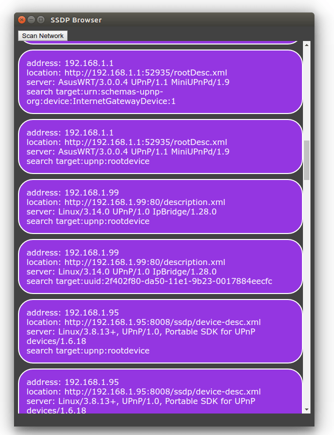
Enough code has been shared for the sample to be used, but rather than rely on the development JavaScript console,  I’ll change the sample to show the responses in the UI. To keep it simple I’ve defined the HTML structure that I will use for each result as a child element of a div element of the class palette. This element is hidden, but for each response I’ll clone the div element of the class ssdpDevice; will change some of the child members; and append it to a visible section of the page.

        
 <html>
    <head>
        <link rel="stylesheet" href="styles/style.css" />
        http://./scripts/jquery-3.3.1.min.js
        http://./scripts/MulticastSocket.js
        http://./scripts/app.js
    </head>
    <body>
Scan Network


</div>

address:
location:
server:
search target:

</div> </div>

</body> </html>


The altered function for that will now display the SSDP responses in the HTML is the following.

        function beginSSDPDiscovery() { 
            if (searchSocket)
                return;
            $('.responseList').empty();
            searchSocket = new MulticastSocket({address:SSDP_ADDRESS, port:SSDP_PORT});
            searchSocket.onDiagram = function(arrayBuffer, remote_address, remote_port) {
                console.log('response from ', remote_address, " ", remote_port);
                var msg = searchSocket.arrayBufferToString8(arrayBuffer);
                console.log(msg);
                discoveryData = discoveryStringToDiscoveryDictionary(msg);
                console.log(discoveryData);
        
                var template = $('.palette').find('.ssdpDevice').clone();
                $(template).find('.ipAddress').text(remote_address);
                $(template).find('.location').text(discoveryData.location);
                $(template).find('.server').text(discoveryData.server);
                $(template).find('.searchTarget').text(discoveryData.st)
                $('.responseList').append(template);
            }
            searchSocket.connect({call:function(c) {
                console.log('connect result',c);
                searchSocket.sendDiagram(SSDP_REQUEST_PAYLOAD,{call:()=>{console.log('success')}});
                setTimeout(endSSDPDiscovery, 5000);
            }});    
        }    

Working with non-SSL Web Services within an SSL page

I was making a Progressive Web App (PWA) and encountered a problem pretty quickly.  PWAs need to be served over SSL/HTTPS.  The services that they access must also be served over SSL (a page served over SSL cannot access non-SSL resources).  Additionally, since my app is being served from a different domain, there must be a Cross Origin Resource Sharing header permitting the application to use the data.  My problem is that I ran into a situation where I needed to access a resource that met neither of these requirements.

Failed to load http://myUrl.com: No 'Access-Control-Allow-Origin' header is present on the requested resource. Origin 'http://SomeOtherURL.com' is therefore not allowed access.

The solution to this seemed obvious: a proxy service that would consume the non-SSL feed and make the results available over HTTPS.  There exists some third party services that can do this for you (My SSL Proxy, for example).  But the services that I found were not meant for applications and generally don’t add the required CORS headers.  Implementing something like this isn’t hard, but for a lightweight application for which I wasn’t planning on making any immediate revenue, I wanted to minimize my hosting costs.  This is where two services that Google provides come into play.

The first Google service is Firebase.

Firebase (available at https://Firebase.Google.com) allows you to host static assets in the Google cloud.  These assets are servers over SSL.  This was a perfect place for hosting most of the source code that was going to run on the mobile device.

As for the service proxy, I made a proxy service that ran on the second Google service: App Engine.  Google’s cloud service App Engine (available at https://cloud.google.com/appengine/) allowed me to write my proxy service using NodeJS (available at https://nodejs.org/).  I had it query the data I needed from the non-SSL service and cache the data for 30 seconds at a time.  All of Google’s services use SSL by default, so I didn’t have to do anything special.  When returning the response I added a few headers to handle CORS requirements.  Here’s the code for the node server.  If you use it, you will need to modify it so that any parameters that you need to pass to the non-SSL service are passed through.

const http = require('http')
const port = 80;
const MAX_SCHEDULE_AGE = 30;
const SERVICE_URL=`YOUR_SERVICE_URL`

var schedule = '[]';
var lastUpdate = new Date(1,1,1);


function timeDifference(a,b) { 
    var c = (b.getTime() - a.getTime())/1000;
    return c;
}

function sendSchedule(resp) {
    resp.setHeader('Access-Control-Allow-Origin', '*');
	resp.setHeader('Access-Control-Request-Method', '*');
	resp.setHeader('Access-Control-Allow-Methods', 'OPTIONS, GET');
	resp.setHeader('Access-Control-Allow-Headers', '*');
    resp.end(schedule);
}
const requestHandler = (request,response) => {
    var now = new Date();
    var diff = timeDifference(lastUpdate, now);
    if(diff>MAX_SCHEDULE_AGE) {
        console.log('schedule is stale. updating');
        sendSchedule(response);
        return;
    }
    updateSchedule((d)=> {
        console.log('schedule updated')
        sendSchedule(response);
    });
    console.log(request.url);

}

const server = http.createServer(requestHandler);

const https = require('https');


function updateSchedule(onUpdate) { 
    https.get(SERVICE_URL, (resp) => {
        let data = '';
        resp.on('data', (chunk) => {
            data += chunk;
        });
        resp.on('end', ()=> {
            schedule = data;
            lastUpdate = new Date();
            if(onUpdate) {
                onUpdate(schedule);
            }
        })
    });
}

server.listen(port, (err) => {

    if(err) {
        return console.log('something bad happened');
    }
    console.log(`server is listening on port ${port}`);
    updateSchedule();
}) 

One of the other advantages of having this proxy service is that there is a now a layer for hiding any additional information that is necessary for accessing the service of interest.  For example, if you are communicating with a service that requires some key or app id for access, that information would never flow through to the client.

Some configuration was necessary for deployment, but not much.  I had to add a simple app.yaml file to the project.  These are the contents.

# [START runtime]
runtime: nodejs10
# [END runtime]

Deployment of the application was unexpectedly easy.  I already had the source code stored in a git repository.  App Engine exposes a Linux terminal through the browser.  I cloned my repository and typed a few commands.

$  export PORT=8080 && npm install
$  gcloud app create
$  gcloud app deploy

After answering YES to a configuration prompt, the application was deployed and running.

One might wonder why I have the code for my application hosted in two different services.  I could have placed the entire thing in App Engine.  My motivation for separating them is that I plan to have some other applications interface with the same service.  So I wanted to keep the code (for specific clients of the code) separate from the service interface.

Linux On Dex: Works on WiFi Tab S4 Models Only

Update 2018-Dec-11: I’ve spoken to a LoD team member and to jump straight to the point of you have a LTE Tab S4 then simply put the required update isn’t available at this time and there is no information on when it will be available.

Some people trying to install Linux on Dex are running into an obstacle. After installing he app and trying to run it they get the following error message.

Linux on Dex requires your device to have the latest software o support some features.

After this message is acknowledge the application closes. If someone with this error checks for updates in the app store or for updates to the operating system they get notification that everything is up to date. What’s going on? I contacted LoD support about this and got back the following response.

Currently, the Linux on DeX(beta) requires latest SW for Galaxy Note9 and Galaxy Tab S4. SW update schedule may vary depends on the region and carrier.

Currently, the Linux on DeX(beta) requires latest SW for Galaxy Note9 and Galaxy Tab S4.
SW update schedule may vary depends on the region and carrier.

What does this mean? It means that your device doesn’t have a update that is required for DeX and that your carrier might not have released it.  Devices sold through a carrier can be a bit slower in receiving their updates. Samsung hasn’t been specific on the updated needed.  I’ve communicated with someone on the Linux on Dex team and was told that LTE tablets in general do not have the update that is required for Linux on Dex. Additionally the person told me that there is no information available on when particular updates will work their way through certain carriers.

BTW: Unlocking your device and installing a SIM from another carrier will not change this; this behaviour is dependent on the carrier for which the device was made, not on the SIM that happens to be in the device at the time.

Samsung Announced Exynos 9 with NPU


Consistent with what they said at the developer’s conference about wanting to extend the reach of their A.I. Samsung has announced a new System on Chip (SoC) with some A.I. related features. The Exynos 9 Series 9820 processor. The processor contains an NPU, a unit for processing neural networks at speeds faster than what could be done with a general purpose processor alone. The presence of this unit on the device hardware makes possible device side experiences that would have previously required that data be sent to a server for processing. This may also translate into improvements in AR and VR experiences.

The NPU isn’t the only upgrade that comes with the processor. Samsung says the 9820’s new fourth generation custom core delivers a 20% improvement in single core performance or 40% in power efficiency compared to is predecessor. Multicore performance is said to be increased around 15%. The Exynos 9820 also has a video encoder capable of decoding 4K video at up to 150 frames per second in 10-bit color. The processor goes into mass production at the end of this year.

Source: Samsung

Bixby Developer Studio

Samsung says they would like to have AI implemented in all of their products by 2020. From the visual display shown during the SDC 2018 conference it appears their usage of “all” is intended to be widely encompassing. Phones, car audio systems, refrigerators, air conditioners…

Samsung is inviting developers to start engaging in development for their conversational AI. Now they have made the same tools that they use for Bixby development internally available publically. The development portal and the development tools for Windows and OS X are available now at: https://bixbydevelopers.com

Galaxy Home, a Bixby enabled smart speaker, was showcased as a target implementation for the SDK.

The “Media Control API” will be available to content partners this December for adding deeper control into applications. Samsung says Netflix and Hulu are on board and will begin development with it next year.

The Samsung Frame TVs are also being opened to developers by way of the Ambient Mode SDK. This will allow developer content to show when the TV is in it’s standby mode.

Samsung HOLOLAB

1T3A0114.JPG

One of the technology implementations displayed at SDC 2018 was their HOLOLAB. Curious as to what it is I walked over. It was a rig for performing 3D scanning of subjects. A few of the tangible outcomes included some pretty elastic 3D printed statues of people, a volume metric display showing a subject, and a display showing one of the scanned subjects dancing.

I was more curious about the implementation. I got a picture peering into the space to see how the physical structure was built. Inside the space the ambient lighting was ramped up by way of LEDs distributed around the space and 52 Point Grey Research cameras, all mounted to various places on an 8020 rig.

The software is custom built. I asked of its commercial availability and the Samsung rep I spoke to told me, “it was a work in progress.” The rep indicated that they are planning to have some popup locations available in the future for more people to try it and receive a copy of their models.

It is still early in the conference, but I might take a moment to try it out myself.

1T3A0122.JPG
Inside the HoloLab

1T3A0115.JPG


Tizen 5.0 Released

Tizen-Pinwheel-On-Light-RGB

Tizen 5.0 was released a few days ago. This is a week in advance of the Samsung Developer’s Conference 2018. For those keeping count until now the most recent version of Tizen prior to now (4.0) could be found on the Galaxy Watch and Samsung TVs. There are Mobile devices that run Tizen. But I am in the USA and those devices are not sold here (so I won’t speak on them much).

What’s new in Tizen 5.0?  There is improved IoT support, support for Bixby, and support for glTF. glTF is a format that aims to provide efficient loading of 3D scenes, but it is being added to Tizen with intent for it to be applied to watch faces.  With the upgrade we are also getting improved debugging support and a new version of Tizen.Net.  It also looks that they are deprecating the UI Builder tool in Tizen.

I get the feeling that I’ll hear more about this update when I go to the conference next week. I’ll post more from the conference as I find out 🙂

  • C# API for Display Control
  • Native API for Multi-LED control
  • Compressed File System
  • Low Memory Management
  • Upgrade to source libraries
    • icu (60.2)
    • sqlite (3.24.0)
    • json-glib (1.4.2)
    • wayland (1.15.0)
    • efl (1.21)
  • Updated Watchface Complication Framework
  • App Control API
  • Minicontrol API
  • WebView Control added
  • Network Firewall
  • Bluetooth 5.0
  • Neural Network Runtime

Samsung Developer Conference 2018 Registration Open

I previously mentioned that the dates for the Samsung Developer’s conference were announced. Registration is now open.  If you register before September 12 you can register for the lowest available price. The registration form is available over at https://www.samsungdeveloperconference.com/ . Registration is also possible on site. Currently Registration is 299 USD (+tax). After the 12th it will go up to 399 USD. On site registration is 499 USD.

Registration for the Samsung Developer's Conference, 2018

Obtaining the Connection String for a Provisioned Windows IOT Device

Playing with the code that I was using to get data from my car and stream it to the cloud I did something that I knew was a no-no; I hard coded the connection string in the code. There’s a number of reasons to not do this*; it’s less secure as someone can potentially extract the connection string and use it for unauthorized access and if the connection string ever needs to change then code needs to be recompiled and redeployed.

When a Windows IOT device is provisioned there is a connection string that is managed by the device; your application can take advantage of this and need not worry about the details of how it is stored. To make use of this there are a few libraries that you need to add to your UWP project. These include the followings.

  • Microsoft.Azure.Devices
  • Microsoft.Azure.Devices.Client
  • Microsoft.Devices.Tpm

With the classes in these libraries you can obtain the ID of the device and then use that ID to request an Azure DeviceClient class that is initialized with the connection string that the device is managing.

Here’s the code to do this.

DeviceClient _deviceClient;

void InitClient()
{            
    TpmDevice tpm = new TpmDevice(0);
    string hostName = tpm.GetHostName();
    string deviceId = tpm.GetDeviceId();
    string sasToken = tpm.GetSASToken();            
    var client = DeviceClient.Create(
        hostName, 
        AuthenticationMethodFactory.CreateAuthenticationWithToken(deviceId, sasToken),
        TransportType.Mqtt
    );
}

Connecting to Bluetooth RFCOMM with UWP

Soon I will be finished with a project for streaming engine data from a car and into an Azure Data Lake for analysis. I plan to post the full code for this project. But before I do I wanted to talk just about making the Bluetooth connection. The last time I wrote on this procedure it was for a Windows phone 8 project. While part of the UWP ancestry the method of connection in that project would not work in a UWP application today. Things have changed since then and the code that I used there for establishing a connection would not work today.  Treat the code used in this project as psuedo-code for now. While it was copied from a working project I’ve done some modifications to simplify it and focus on a few things here.

Getting information from the engine is easy. Every car sold in the USA (and many  parts of the world) have a diagnostic connector that can be used to query various data from the car. Getting this data is just a matter of having an interface that uses what ever protocol (there’s more than one) that your car happens to use. Don’t worry, it’s not necessary to figure this out yourself. There are products that will abstract this away and provide a common interface and protocol that can be used to communicate with all of these different protocols. One of the most popular solutions is based on a chip-set known as the ELM327. Solutions based on the ELM327 (or an ELM327 clone) will give you a serial interface through which you can send AT commands and other queries to get this information. The products that I am using use a Bluetooth interface for communicating with a computing device. You can also find implementations that use WiFi and RS232.

For development and testing there’s going to be a lot of time spent with a computer in or near a car (unless you also go out and purchase an OBD emulator). To minimize the amount of time that you have to spend around a car you may want to power one of the adapters outside of a car. I did this using a battery (sometimes a power supply) and and an OBD wire harness. Pin number 4 on the harness needs to be connected to ground and pin 16 to positive. A voltage range of 9 to 16 volts should work fine. With the device connected to power you can query information about the device itself but nothing about the car.  While this doesn’t sound very useful at first it’s enough to get the basic Bluetooth connectivity code working.

OBDSetup

For development hardware I am using a Dragonboard 410x running Windows IOT. The UWP based solution, while targeting Windows IOT, runs just fine from a PC. I believe it will run fine from a Raspberry Pi 3 also. Just for fun I tried an old Windows 10 device that I still have in the house and the code ran without any modifications needed from there. So grab what ever Windows 10 device that you have and try it out!

For the application to be able to connect to the device over Bluetooth there are some capabilities that must be declared in the UWP application. I don’t suggest using the Visual Studio for doing this. It doesn’t expose all of the necessary capability settings that are needed. It’s easier to do this in the text editor.

Right-clicking on the project’s manifest gives the option to open it in the code editor. Scrolling down to the Capabilities section I added the following. Some of these properties are needed to access the Bluetooth serial port. Some others are there because they are parts of the project that I will talk about in future post.

  
  <Capabilities>
    <apability Name="internetClient" />
    <DeviceCapability Name="bluetooth" />
    <DeviceCapability Name="proximity" />
    <DeviceCapability Name="location" />
    <DeviceCapability Name="bluetooth.rfcomm">
      <Device Id="any">
        <Function Type="name:serialPort" />
      </Device>
    </DeviceCapability>
  </Capabilities>

I had already paired the Bluetooth device with my Windows IOT device. While the devices are paired with each other the application doesn’t know about the pairing. It still needs to discover the device. To do this I use a device watcher to scan for devices. I know the one that I want to find is named “OBD”. I’ve hard coded this into my solution. The end solution that I’m making doesn’t have a UI, If it did then I would have also made use of the UI that allows a user to select a device being paired.

DataReader _receiver;
DataWriter _transmitter;
StreamSocket _stream;
DeviceWatcher _deviceWatcher;

string[] requestedProperties = new string[] { "System.Devices.Aep.DeviceAddress", "System.Devices.Aep.IsConnected" };
_deviceWatcher = DeviceInformation.CreateWatcher("(System.Devices.Aep.ProtocolId:=\"{e0cbf06c-cd8b-4647-bb8a-263b43f0f974}\")",
                                               requestedProperties,
                                               DeviceInformationKind.AssociationEndpoint);
_deviceWatcher.Stopped += (sender,x)=> {
    _isScanning = false;
    Log("Device Scan Halted");
};
EngineDataList.Add("started");
_deviceWatcher.Added += async (sender, devInfo) =>
{
    Log($"Found device {devInfo.Name}");
    System.Diagnostics.Debug.WriteLine(devInfo.Name + "|" + devInfo.Kind + "|" + devInfo.Pairing);
    if (devInfo.Name.Equals("OBDII"))
    {
     // More Code Goes Here
     //Lets talk about that in a sec
    }
};

_deviceWatcher.Start()

The above code will give result in the DeviceInfo object for the Bluetooth adapter being returned. Now we can connect to it and open up streams for reading and writing. The code for creating these streams would be where I have the comment placed in the above. The following is the code that would go in that place.

try
{
    DeviceAccessStatus accessStatus = DeviceAccessInformation.CreateFromId(devInfo.Id).CurrentStatus;
    if (accessStatus == DeviceAccessStatus.DeniedByUser)
    {
        Debug.WriteLine("This app does not have access to connect to the remote device (please grant access in Settings > Privacy > Other Devices");
        return;
    }
    var device = await BluetoothDevice.FromIdAsync(devInfo.Id);
    Debug.WriteLine(device.ClassOfDevice);

    var services = await device.GetRfcommServicesAsync();
    if (services.Services.Count > 0)
    {
        Log("Connecting to device stream");
        var service = services.Services[0];
        _stream = new StreamSocket();
        await _stream.ConnectAsync(service.ConnectionHostName,
        service.ConnectionServiceName);
        _receiver = new DataReader(_stream.InputStream);
        _transmitter = new DataWriter(_stream.OutputStream);
        
        ReceiveLoop();
        QueryLoop();
        _deviceWatcher.Stop();
    }
}catch(Exception exc)
{
    Log(exc.Message);
}
catch
{
    Log("Native Error");
}

After this runs the devices are connected to each other. The devices would interact by the Win IOT device sending a query and getting a response. For now the only query that will be sent is the string “AT\n”. On devices that accept AT command sets the command AT should only result in the response OK. This is useful for testing the connection without actually having the device perform an operation that would change the state of the system being used.

void QueryLoop()
{
    Task t = Task.Run(async () =>
    {
        
        while (true)
        {
            _transmitter.WriteString(msg);
            _transmitter.WriteString("\r");
            await _transmitter.StoreAsync();
            await Task.Delay(50);
        }
    }
    );
}

void ReceiveLoop()
{
    Task t = Task.Run(async () => {
        while (true)
        {
            uint buf;
            buf = await _receiver.LoadAsync(1);
            if (_receiver.UnconsumedBufferLength > 0)
            {
                string s = _receiver.ReadString(1);
                receiveBuffer.Append(s);
                if (s.Equals("\n")||s.Equals("\r"))
                {
                    try
                    {
                      Debug.WriteLine("Message Received:"+receiveBuffer.ToString());
                        receiveBuffer.Clear();
                    }
                    catch(Exception exc)
                    {
                        Log(exc.Message);
                     
                    }
                }
            }else
            {
                await Task.Delay(TimeSpan.FromSeconds(0));
            }
        }
    });
}

When the above runs the debug output stream will print a series of OK responses. To do something more useful with it we need to know what commands to send to it and how to parse the responses. If you send the command 01 0C while the adapter is connected to a car you will get back a hex response that starts with 41 0C followed by some additional hex numbers. The additional hex numbers are the RPMs of the car. That’s one of the metrics I started off querying because it’s something that I can change without driving the car; for this I can pull the car out of the garage, put it in the driveway, and rev the engine without worrying about carbon monoxide poisoning. I’ll talk about how to find out what metrics that you can query in your car in my next post on this project.

ELM327 Bluetooth Adapter on Amazon

Samsung Developer Conference 2018 Dates

sdc2017logo

The dates for the 2018 Samsung Developer Conference have been announced. Outside of the dates and the location (which has been the same over the past several years) there’s not any additional information available. But if you think you might go now is the time to mark your calendars.

It’s November 7 and 8. That is a Wednesday and Thursday. As per usual it is going to be in the Moscone conference center (the West conference center).

Kernel Filters in HTML+JavaScript

BalloonHeader

Download Code

Kernel filters are a common approach for modifying images for various applications of image processing. They can be used to sharpen an image, blur it, or extract attributes about a picture for further processing. Implementation of the filters is simple and straight forward. I wanted to do some experiments with Kernel filters on my phone. But to my surprise the available options were not many. I decided to make my own. Before developing something for my phone I started off from a browser since my Chromebook was handy. Here I’m sharing the results.

What is a Kernel

Kernels are known by many names. Kernel, convolution matrix, and mask all refer to the same thing. Convolution is the process of adding together the values of neighboring elements of an image and applying some weight to each of the pixels. The weights, or kernel, are often expressed using matrix notation. For each one of the pixels in an image the kernel is applied to the pixel and it’s neighboring pixels to determine the new intensity for the pixel.

Manipulating Images in HTML and JavaScript

In HTML and JavaScript the image element doesn’t give direct access to its pixels for manipulation. Instead the canvas element can be used to read and write pixels. Well, not directly. With the canvas element there’s a method named getPixelData() that will return a structure that has a number array of the intensities of the pixels. After manipulation of the elements the the result can be copied back into the canvas with putPixelData().

Visually we see the pixel data as being organized in rows and columns. In memory it is organized in a single dimensional array. To read and write the correct pixel you’ll need to know how it’s organized. A single pixel is composed of 4 numbers; 3 of the numbers are for intensities of red, green, and blue and the fourth number is for transparency. These 4 elements make up a single pixel. Pixel data is usually saved continuously starting with the upper left most pixel of an image as the first one to be encoded and moving to the right from there. Once the end of a row is reached the encoding continues starting with the left most pixel on the next row.

Pretend that you had an image that was 10 pixels wide and 10 pixels tall. If you wanted to read from the pixel on the third row and fourth column (keeping in mind that zero based addressing is being used) we would need at least 20 pixels into the array to get to the third row and then another 3 more pixels to get to the fourth column. In other words we need to read the twenty third pixel. Since pixels are composed of four elements this works out to the reading starting with index 92 of the array to get the red portion of the pixel and indices 93, 94, and 95 to read the green, blue, and transparency portions. Given an X and Y coordinate the equation for determining what address to start reading at is as follows.

PixelIndex = (y*imageWidth+x)*4;

Since the application of the kernel can overlap with pixels that are outside the range of the image I needed to decide how to deal with attempts to read pixels that are outside of range. I could have a constant value returned (like zero for all elements), have the read address wrap around to the other side of the image, or I could cap the read coordinates. I chose to cap the read coordinates. Attempts to read a coordinate that is less than zero will result in coordinate being changed to zero. An attempt to read beyond the edge of the image results in the edge of the image being read.

I’ve covered enough theory for us to build our first kernel filter in JavaScript. Now to get to building. Kernel filters are arrays of multipliers. They can be of any dimension. The basic pieces of information that we’ll need are the dimensions of the kernel and an array holding the values for each element of the kernel. We also need to mark which position in a filter represents the center pixel.

function kernel(width, height, centerX, centerY) {
	this.width = width;
	this.height = height;
	this.centerX = centerX || Math.floor(height/2);
	this.centerY = centerY || Math.floor(width/2);
	this.weightArray = [];
	for(var h=0;h<height;++h) {
		this.weightArray.push([]);
		for(var w=0;w<width;++w) {
		 	this.weightArray[h].push(0);
		}
	}
}

Given an image we need to get the image data from the image into the canvas. The canvas has a method named drawImage that will do this.

var width  = imageElement.naturalWidth;
var height = imageElement.naturalHeight;   
var canvas = $('')[0];
var ctx = canvas.getContext('2d');
ctx.drawImage(img,0,0);
var image = ctx.getImageData(0,0,width,height);
var pix = image.data;

To apply the filter, we will need to have a structure that contains the source data and another for writing the results. The results cannot be written to the same structure that we are reading from as this would overwrite some of the pixels that still need to be read for other processing.

var getPix = function(x,y) {
      x = Math.max(0, Math.min(x, width -1));
      y = Math.max(0, Math.min(y, height-1));
      var address = (y*width+x)*4;
      return [pix[address+0], pix[address+1], pix[address+2], pix[address+3]];
    }
    
    var getFilteredPix = function(x,y, kernelFilter) {
      var retVal = [0,0,0,0];
      for(var fy=0;fy<kernelFilter.height;++fy) {
        for(var fx=0;fx<kernelFilter.width;++fx) {
          var m = kernelFilter.weights[fy][fx];
          var pix = getPix(x+fx-kernelFilter.centerX, y+fy+-kernelFilter.centerY);
          retVal[0]+=pix[0]*m;
          retVal[1]+=pix[1]*m;
          retVal[2]+=pix[2]*m;
          retVal[3]+=pix[3];
        }
      }
      return retVal;
    }
    
    for(var yp=0;yp<height;++yp) {
      for(var xp=0;xp<width;++xp) {
        var newVal = getFilteredPix(xp,yp);
        var address = (yp*width+xp)*4;
        resultPixelData[address+0] = newVal[0];
        resultPixelData[address+1] = newVal[1];
        resultPixelData[address+2] = newVal[2];
        resultPixelData[address+3] = newVal[3]
      }
    }

With that in place we can now view the results of various kernel filters. Using the same source image here are a few filters and the result of them being applied. This is the original image that I’ll be working with.

balloon

Identity

0 0 0
0 1 0
0 0 0

As suggested by the name the identity filter does not result in any change on
the image, much like other identity operations in math like adding 0 to a number
or multiplying and dividing by 1.

balloon

Edge Detection

-1 -1 -1
-1 8 -1
-1 -1 -1

The edge detection filter highlights high contrast areas of an image resulting in lines
showing where these areas meet. If you wanted to produce an outline of a subject this
would be one of your go-to filters.
balloonEdge


Emboss

-2 -1 0
-1 1 1
0 1 2

The Embose filter produces an image with a 3d effect making it look like the image has been pressed into a material. Various areas of the image will appear to be raised or depressed.

balloonEmbose

Box Blur

0.111 0.111 0.111
0.111 0.111 0.111
0.111 0.111 0.111

The Box Blur simply averages the pixels in an area together. Here I show a 3×3 filter. For the image shown here I actually used a 10×10 filter for the sake of exagerating the effect to make it more visible here.

balloonBlur

This gives me something quick I can use for testing out image filters. It could be better though. Right now, to apply a different filter I need to modify code. Wouldn’t it be nice if the filter data were externalized allowing for filters to be saved and shared? I’ll look at that the next time I revisit this project.

GTX 1050, WDDM 2.2, and Windows Mixed Reality

Update

It took a lot more digging, but I did find the source of this problem. While the video card *did* match requirements the problem was the processor generation. Since it was below the required generation there were some features that were not enabled in the video card drivers. Since some features were not enabled in the video card drivers the video card itself appeared to not meet requirements.

Original

I’ve got some Windows Mixed Reality Immersive headsets in hand. The experience is pretty cool. But I wanted to figure out what the minimum requirements are to use them so that we could get new hardware for some of the other developers. Microsoft has minimum requirements listed on a page. Not being one to take such a thing on word value (especially not for a new product) I decided to validate these requirements. The item I was questioning was the video card. The requirements list the NVidia GTX 1050 as the minimum video card. I made my way over to my local Best Buys and picked one up.

It was installed into a Machine that already had the Windows 10 Creator’s Update on it. When I started the Mixed Reality application I got the following.

CantRunMixedRality

I tried several driver versions from the ones released in April (version 381.65, which were the first to have VR support) to the most recent at the time of this writing (385.28).

Digging a little deeper I received a rather cryptic message from the NVidia GeForce software on Virtual Reality support. The software told me that this video card didn’t meet requirements for Virtual Reality. I needed to have at least an NVidia GTX 1050, and the card in the machine was only a NVidia GTX 1050. That’s not a typo, it showed the same card for both the required minimum and what was installed. I get the impression that there was the intention to support VR in this card but it just never happened.

As of yet the consumer release of the Mixed Reality features has not occurred. We are still in a time frame in which things could change rapidly. This card might be supported by then. From some exchanges with others though of you are looking to get a card that supports the Windows Mixed Reality headsets start of with NVidia’s GTX 1060 as a minimum.


Using PowerShell to Setup SpectatorView

SpectatorViewSetup

I have some down time and spent some of the time to clear the drive on a computer, reinstall Windows, and rebuild my development environment. While I was doing this I decided to try out SpectatorView for the HoloLens. For those unfamiliar SpectatorView is a solution for creating recordings of what one sees through a HoloLens. The HoloLens does have a recording feature built in, but that feature is low resolution. Using SpectatorView one can produce a high resolution recording. Using a high resolution camera mounted to a HoloLens and a video capture a computer takes the motion data stream from the HoloLens to overlay objects from a HoloLens program onto a video stream. I tried it out last week with a 1K camera (Canon 5D Mark III) and it works great!

One of the personal goals that I have is that when possible to automate setup steps for a development environment, especially if I may need to do them again. I expect to see a fast return on investment for doing this either through time saved when I seed to setup an environment for myself again or when coworkers are able to save time by being able to use the scripts that I’ve made. Up until now my use of PowerShell has been light, but it looked to be the perfect scripting language for this task. For the most part PowerShell gives access to the COM, WMI, and .Net objects in a scripted environment.

Software and Files Needed for Spectator View

To setup SpectatorView there are a number of software components that are needed.

    • Visual Studio
    • Unity
    • BlackMagic DeckLink SDK
    • Hololens Companion Toolkit
    • Hololens Toolkit
    • OpenCV 3.2
    • Canon SDK (Optional)

Unity and Visual Studio are frequently used within my team, so I’m starting off with the assumption that these two components are already present. Getting the other components is easy enough, so I don’t expect an attempt at scripting the acquisition and installations for it to save much time. But I also feel that initial attempts at scripting are better applied to something simple to allow for problems to be found before being applied to more complex scenarios. The Canon SDK can only be downloaded if someone registers with Canon, requests access to the SDK, and then downloads the SDK after receiving approval to download the SDK. Since there are manual steps involved in getting access to the Canon SDK I did not script the acquisition of the file. Similarly the BlackMagic Decklink SDK also requires registration to download. While I could not script the acquisition of these two files I was still able to handle them post download in my script. Each version of these SDKs have a slightly different name since the version number is a part of the file name. To keep the script easy to use it will figure out the actual name of the file when run. If a new version of one of the SDKs were to be used it would only be necessary to replace the ZIP file being used.

Cloning the HoloLend Companion Kit with github

The Hololens Companion Kit is the easiest of the components to acquire through a script. It can be downloaded using GIT. So I won’t spend much time talking about how to download it and only mention it at all since it is a necessary component.

$openCVUrl = "https://downloads.sourceforge.net/project/opencvlibrary/opencv-win/3.2.0/opencv-3.2.0-vc14.exe?r=http%3A%2F%2Fopencv.org%2Freleases.html&ts=1501614414&use_mirror=iweb";
$companionKitFilePath = $PSScriptRoot + "\HoloLensCompanionKit";
$kitIsDownloaded = Test-Path $companionKitFilePath;
if(!$kitIsDownloaded) {
	git clone $hololensCompanionKitURL;
}

If you are not familiar with what the Test-Path command means don’t worry about it just yet. I’ll explain it’s use when it is used on another component.

File Paths

Leaving nothing to be ambiguous many of the file locations referenced are relative to the location of the power script file. In PowerScript There is a variable named $PSScriptRoot whose value is the full path to the folder from which the script is run. While not absolutely necessary I build paths to various files and folders using this variable.

Downloading OpenCV

For downloading the OpenCV source I’ve placed the URLs for OpenCV from one of the mirrors in a variable at the top of my script. If I ever wanted to change the version of OpenCV used I would need to change the value in this variable. There are several ways to download a file in PowerScript. I decided to use .Net’s WebClient because of speed and predictability. I considered using BITS but when using BITS to download you can’t know when the service will get around to downloading the file; it will do so on it’s own schedule. Downloading the file with the WebClient is easy. But it provides no feedback while it works. Just so that someone using the script doesn’t think that something is wrong I decided to print a message letting them know to hold on for a moment.

$openCVUrl = "https://downloads.sourceforge.net/project/opencvlibrary/opencv-win/3.2.0/opencv-3.2.0-vc14.exe?r=http%3A%2F%2Fopencv.org%2Freleases.html&ts=1501614414&use_mirror=iweb";			
$webClient = New-Object System.Net.WebClient;
$openCVArchivePath = $openCVFolder + "\archive.exe"
Write-Host "Downloading OpenCV. This is going to take a while..." -foreground "Green"
$webClient.DownloadFile($openCVUrl,$openCVArchivePath );

If you were to take the above and put it in a file with a “ps1” extension and run it you’ll find that a file downloads named archive.exe. OpenCV for Windows is distributed in a self extracting archive (Which is why it uses an EXE extension instead of ZIP). Once the files is downloaded if you were to run it you would be greeted with a prompt asking where you want the file to be extracted. For automating the setup I don’t want the archive to give these prompts. I’ll invoke it passing to it on the command line the location that it should use. Adding those arguments to the above script we end up with the following.

$openCVUrl = "https://downloads.sourceforge.net/project/opencvlibrary/opencv-win/3.2.0/opencv-3.2.0-vc14.exe?r=http%3A%2F%2Fopencv.org%2Freleases.html&ts=1501614414&use_mirror=iweb";			
$webClient = New-Object System.Net.WebClient;
$openCVFolder = "${PSScriptRoot}\openCV\openCV3.2"
$openCVArchivePath = $openCVFolder + "\archive.exe"
Write-Host "Downloading OpenCV. This is going to take a while..." -foreground "Green"
$webClient.DownloadFile($openCVUrl,$openCVArchivePath );
Write-Host "Download complete";
& "${openCVArchivePath}" -o "${openCVFolder}" -y

This works. But i wanted it to be possible to run this script more than once if it failed for some reason. To prevent the script from reinstalling OpenCV again if it had been installed before I check for the existence of the OpenCV folder. This is a less than thorough test as it would not detect conditions such as an archive being partially unzipped before failing. But this is satisficing for my purposes. The Test-Path< command can be used to determine whether or not a file object exists at some path. I wrapped the above code in a block that checks for the existence of the OpenCV folder first.

$openCVIsDownloaded = Test-Path $openCVFolder
if(!$openCVIsDownloaded) {
	## Download code goes here
}

Unpacking the Canon and BlackMagic SDKS

The BlackMagic and Canon SDKs are both in ZIP files. Unpacking them will be about the same. I’ll only talk about the Canon SDK for a moment. But the there’s equal applicability to what I am about to say to both. Like the OpenCV SDK I’ll check to see if the folder for the Canon SDK exists before trying to unpack it. The script requires that the Canon SDK zip file be in the same folder as the script. The Canon SDK versions all start with the same prefix. They all start with EDSDK. To find the file I use the Get-ChildItem command to get a list of files. If there is more than one version fo teh SDK in the folder sorting the results and taking the last should result in the most recent one being selected. PowerShell allows the use of negative index numbers to address an item from the end of a list. Index -1 will be the last item in the list. Taking the last item and getting its FullName value will give the path to the zip file to be unzipped. The Expand-Archive command will unzip the file to a specified path.

################################################
# Unpacking the Canon SDK
################################################
$CanonSDKIsPresent = Test-Path "${PSScriptRoot}\CanonSDK";
if(!$CanonSDKIsPresent)
{
	#Find the Canon SDK Zip(s) present
	$canonSdkArchiveList = Get-ChildItem "${PSScriptRoot}\EDSDK*.zip" | Sort;
	$canonSDKZip = $canonSdkArchiveList[-1].FullName
	Expand-Archive  -path $canonSDKZip -DestinationPath "${PSScriptRoot}\CanonSDK";
} 
################################################
# Unpacking the Black Magic SDK
################################################
$BlackMagicSDKIsPresent = Test-Path "${PSScriptRoot}\BlackMagicSDK";
if(!$BlackMagicSDKIsPresent) 
{
	#Find the Black Magic SDKs present
	$blackMagicSDKList = Get-ChildItem "${PSScriptRoot}\Blackmagic_Decklink_SDK*.zip";
	$blackMagicZip = $blackMagicSDKList[-1].FullName;
	Expand-Archive  -path $blackMagicZip -DestinationPath "${PSScriptRoot}\BlackMagicSDK";
}

Modifying the Visual Studio Dependencies File

The Visual Studio project that is part of the SpectatorView software requires some updates so that it knows where the various SDKs are located. The path to the BlackMagic SDK, Canon SDK, and OpenCV software must be added to it. The dependencies file dependencies.props is an XML file. The Common Language Runtime has classes for manipulating XML files. I use one of these to update this file. The exact path of each component could differ depending on which SDK version is used. Rather than hard code the path I use the Get-ChildItem command again to query for the name of folders. For the CanonSDK the line of script code to get the path looks like the following.

$canonPath = (Get-ChildItem "${PSScriptRoot}\CanonSDK")[-1].FullName+"\Windows";

There is a little more nesting that occurs with the other two SDKs. But the lines for getting their paths is similar.

$openCVPath = ((Get-ChildItem (Get-ChildItem "${PSScriptRoot}\opencv" | ?{$_.PsIsContainer} )[-1].FullName)|?{$_.PsIsContainer})[-1].FullName+"\sources\include";
$blackMagicPath = (Get-ChildItem "${PSScriptRoot}\BlackMagicSDK" | ?{$_.PsIsContainer})[-1].FullName +"\Windows";

With those paths populated I now need to load the XML file, update the values, and write them back. The Common Language Runtime’s XML class is available to PowerShell. Given a string that contains XML if that string is cast to [xml] it will be parsed and all the nodes available through its properties. To get the XML string from the contents of the dependencies files the Get-Content command will be used. Given a file path it returns the contents as a string.

$dependencies = [xml] (Get-Content -Path "${PSScriptRoot}\${HoloLensCompanionKit}\HoloLensCompanionKit\SpectatorView\dependencies.props");
$dependencies.Project.PropertyGroup[0]."OpenCV_vc14" = $openCVPath ;
$dependencies.Project.PropertyGroup[0]."DeckLink_inc" = $blackMagicPAth;
$dependencies.Project.PropertyGroup[0]."Canon_SDK" = $canonPath;
$dependencies.Save( "${PSScriptRoot}\${HoloLensCompanionKit}\HoloLensCompanionKit\SpectatorView\dependencies.props" );

Next Steps

The script is at the bottom of this post. Running this script doesn’t result in SpectatorView being 100% setup. It is still necessary to go through calibration (a step that requires you to physically do some things) in front of the camera) and copying the libraries from the sample project into your own project. There are opportunities for further automating the setup. But I felt this was a good time to write about what is working at this moment (if I wait until it is perfect ot may never get posted).

clear;
################################################
# A few download URLs
################################################
$openCVUrl = "https://downloads.sourceforge.net/project/opencvlibrary/opencv-win/3.2.0/opencv-3.2.0-vc14.exe?r=http%3A%2F%2Fopencv.org%2Freleases.html&ts=1501614414&use_mirror=iweb";
$holoLensCompanionKitURL = "https://github.com/Microsoft/HoloLensCompanionKit";
$webClient = New-Object System.Net.WebClient;
Write-Host "Running from ${PSScriptRoot}";


$companionKitFilePath = $PSScriptRoot + "\HoloLensCompanionKit";
$openCVFolder = "${PSScriptRoot}\openCV\openCV3.2"
$openCVArchivePath = $openCVFolder + "\archive.exe"

$kitIsDownloaded = Test-Path $companionKitFilePath;
if(!$kitIsDownloaded) {
	git clone $hololensCompanionKitURL;
}

$openCVIsDownloaded = Test-Path $openCVFolder
if(!$openCVIsDownloaded) {
	New-Item "$openCVFolder"  -type directory
	Write-Host "Downloading OpenCV. This is going to take a while..." -foreground "Green"
	$webClient.DownloadFile($openCVUrl,$openCVArchivePath );	
	Write-Host "Download complete";
	& "${openCVArchivePath}" -o "${openCVFolder}" -y
}
################################################
# Unpacking the Black Magic SDK
################################################
$BlackMagicSDKIsPresent = Test-Path "${PSScriptRoot}\BlackMagicSDK";
if(!$BlackMagicSDKIsPresent) 
{
	#Find the Black Magic SDKs present
	$blackMagicSDKList = Get-ChildItem "${PSScriptRoot}\Blackmagic_Decklink_SDK*.zip";
	$blackMagicZip = $blackMagicSDKList[-1].FullName;
	Expand-Archive  -path $blackMagicZip -DestinationPath "${PSScriptRoot}\BlackMagicSDK";
}
################################################
# Unpacking the Canon SDK
################################################
$CanonSDKIsPresent = Test-Path "${PSScriptRoot}\CanonSDK";
if(!$CanonSDKIsPresent)
{
	#Find the Canon SDK Zip(s) present
	$canonSdkArchiveList = Get-ChildItem "${PSScriptRoot}\EDSDK*.zip" | Sort;
	$canonSDKZip = $canonSdkArchiveList[-1].FullName;
	Expand-Archive  -path $canonSDKZip -DestinationPath "${PSScriptRoot}\CanonSDK";
} 
else 
{
	Write-Host "Canon SDK already present";
}
################################################
# Modifying the Dependencies File
################################################
$canonPath = (Get-ChildItem "${PSScriptRoot}\CanonSDK")[-1].FullName+"\Windows";
$openCVPath = ((Get-ChildItem (Get-ChildItem "${PSScriptRoot}\opencv" | ?{$_.PsIsContainer} )[-1].FullName)|?{$_.PsIsContainer})[-1].FullName+"\sources\include";
$blackMagicPath = (Get-ChildItem "${PSScriptRoot}\BlackMagicSDK" | ?{$_.PsIsContainer})[-1].FullName +"\Windows";

$dependencies = [xml] (Get-Content -Path "${PSScriptRoot}\${HoloLensCompanionKit}\HoloLensCompanionKit\SpectatorView\dependencies.props");
$dependencies.Project.PropertyGroup[0]."OpenCV_vc14" = $openCVPath ;
$dependencies.Project.PropertyGroup[0]."DeckLink_inc" = $blackMagicPAth;
$dependencies.Project.PropertyGroup[0].= $canonPath;
$dependencies.Save( "${PSScriptRoot}\${HoloLensCompanionKit}\HoloLensCompanionKit\SpectatorView\dependencies.props" );

Resolving Problems Connecting to the Gear S2/S3 for Development

On occasions I develop for the Gear S2/S3 watches from Samsung. (From a development perspective these watches are nearly identical, so I will collectively refer to them as the Gear S watches). When returning to develop after a period away from them there are a few mistakes that I find I sometimes make. Looking in some support forums I see there are others that make these mistakes too. To both help out others that run into this (and as a note to myself) I’ve made this post to cover some of the checks necessary.

  1. Ensure Debugging is Enabled
  2. Ensure Wifi is Always Enabled
  3. Check the watch’s IP address
  4. Ensure the watch is unlocked
  5. Connect to the watch from SDB
  6. Redeploy the development certificate


Ensure Debugging is Enabled

Before anything else will work debugging must be enabled on the watch. This setting will be cleared if you’ve done a hard reset on the watch or if you have connected it to a different phone. You can change the setting by navigating to Settings ➜ Gear Info ➜ Debugging and ensure that the setting is checked.

Ensure WiFi is always enabled

You’ll want to have WiFi set to always on. If you have it set to “Auto” you might not be able to connect. If it is set to “Off” then you will invariably will not be able to connect. Setting WiFi to “Always On” will cause the battery to drain excessively. When developing you’ll want to have the charging cradle close by. To set WiFi to always be on navigate to Settings ➜ Connections ➜ WiFi ➜WiFi and select “Always On.”


Check the Watch’s IP Address

You need to know the watch’s IP address to attach to it for debugging and deployment. Remember that the IP address will be different if you go to a different wireless network or could be different if you reconnect to the same network.  To see the watch’s IP address navigate to Settings ➜ Connections ➜ Wi-Fi ➜ Wi-Fi networks ➜ select your network ➜ scroll down to the IP address.

Ensure the Watch is Unlocked

The watch must be unlocked for the initial connection. While this may be obvious what is less obvious is how quickly the watch can become locked again. The heart rate monitor on the back of the watch also acts as a presence detection sensor; the watch is aware of when it’s been removed from your wrist and will go into a locked state almost immediately if you have a lock code/patter on it. When handling the watch if your finger passes over this sensor the watch may lock. You could unlock the watch, set it down in the cradle, and it could be locked again because of your finger coming close to the sensor.

Heart Rate Monitor on the back of the Gear S2

Connect to the Watch using SDB

Before opening Tizen Studioconnect to the watch using SDB. From the command line on your computer (or Terminal if you are on a Mac) navigate to the folder that contains Tizen Studio and then into the tools folder inside of it. Type the following substituting your own IP address here.

sdb connect 192.168.1.181

If this is the first time the watch has connected to the machine from which you are typing the command the watch will prompt you to accept an RSA key. If you don’t accept it the connection attempt will fail. Sometimes when you attempt to connect the command line tool will print a failure message the first time even though it has actually connected. Run the command a second time and you’ll get a message that the watch is already connected.

Redeploy your Development Certificate

You only need to do this if the watch has been reset since the last time you’ve done development on it (or if you’ve never developed on the watch before).  Certificate management is a topic of it’s own; I won’t go into it here. Provided that you have a handle on development certificates the above should be enough to get your watch connected to your computer for development.