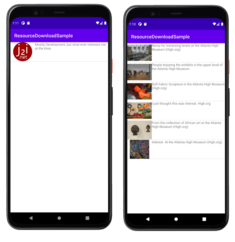
As with any project, I had a list of milestones and dates on which I expected to hit them leading up to project completion. One of the elements for the project was an application that needed to detect its proximity to other devices to select a device for interaction. I planned to use iBeacons for this, and had a delivery date on some beacons for development. The delivery date came, a box with the matching tracking number came, but there were no iBeacons inside. Instead, there was a phone case. This isn’t the first time I have ordered one item and Amazon has sent me another. I went online and filled out a form to have the order corrected. They stated I would have the item in another 5 days. In the mean time, I didn’t want to let progress slip. I’ve heard several times “You can use an iPhone as an iBeacon.” I now had motivation to look into this. You can in fact use a phone as an iBeacon. But you have to write an application yourself to use it this way.
When I took a quick look in the App store, I couldn’t find an app for this purpose. So I decided to make an application myself. It isn’t hard. In my case, I’m emulating an iBeacon as a stand-in for actual hardware. But there are other reasons you might want to do this. For example, if I were using an iPad as a display showing more information on an exhibit users browsing the exhibit could interact with the content on the display using their own phone. The iBeacon signal could be used so that the user’s phone knows which display it is close to, allowing them to trigger interactions from their own phone (a valuable method of interaction given the higher concerns on hygiene and concerns over shared touch surfaces).
Beacons are uniquely identified by three pieces of data; the UUID, Major number, and Minor number. A UUID, or Universally Unique ID, is usually shared among a group of iBeacons that are associated with the same entity. The usage of the Major and Minor numbers is up to the entity. Usually the Major will be used to group related iBeacons together with the Minor number being used as a unique ID within the the set. I’ll talk more about these numbers in another post.
For my iPhone application, I have created a few variables to hold the simulated Beacon’s identifiers. I also have a variable to track whether the iBeacon is active, and have defined a Zero UUID to represent a UUID that has not been assigned a value.
class BeaconManager {

    var objectWillChange = PassthroughSubject<Void, Never>()

    let ZeroUUID = UUID.init(uuidString: "00000000-0000-0000-0000-000000000000")

    var BeaconUUID = UUID(uuidString: "00000000-0000-0000-0000-000000000000") {
        didSet { updateUI() }
    }

    var Major:UInt16 = 100 {
        didSet { updateUI() }
    }

    var Minor:UInt16 = 2 {
        didSet { updateUI() }
    }

    var IsActive:Bool = false {
        didSet { updateUI() }
    }
}
I am going to use Swift UI for displaying information. That is why setting these variables also triggers a call to updateUI(). There are some callbacks that are made by Apple’s iBeacon API. For these, I’ll need to also need to implement the CBPeripheralManagerDelegate. This protocol is defined in CoreBluetooth. We also need permission for the device to advertise its presence over Bluetooth. permission. Bluetooth is often used for indoor location (which will be my ultimate intention). Let’s get all these other things in place. The necessary import statements and inheritance will look like the following.
import Foundation
import CoreLocation
import CoreBluetooth
import Combine

class BeaconManager: NSObject, CBPeripheralManagerDelegate, Identifiable, ObservableObject {
   ...
}
For the Bluetooth permission that the application needs, a new String value must be added to the Info.plist. The item’s key is NSBluetoothAlwaysUsageDescription. The value should be a text description that will be presented to the user letting them know why the application is requesting Bluetooth permissions.
I want the simulated iBeacon to have the same value every time the application runs. At runtime, the application is going to check whether there is a UUID already saved in the settings. If there is not one, then it will generate a new UUID and save it to the settings. From then on, it will always use the same ID. I do the same thing with the Major and Minor numbers using the UInt16.random(in:) function. This information together is used for create a CLBeaconRegion.
    func createBeaconRegion() -> CLBeaconRegion {
        let settings = UserDefaults.standard
        if let savedUUID = settings.string(forKey: BEACON_UUID_KEY) {
            if let tempBeaconUUID = UUID(uuidString: savedUUID) {
                BeaconUUID = tempBeaconUUID
            }
        }
        if(BeaconUUID == nil){
            BeaconUUID = UUID()
            settings.setValue(BeaconUUID!.uuidString, forKey: BEACON_UUID_KEY)
            settings.synchronize()
        }
        let majorValue = settings.integer(forKey: BEACON_MAJOR_KEY) ?? 0
        if(majorValue == 0) {
            Major = UInt16.random(in: 1...65535)
            settings.setValue(Major, forKey: BEACON_MAJOR_KEY)
        }
        let minorValue = settings.integer(forKey: BEACON_MINOR_KEY) ?? 0
        if(minorValue == 0) {
            Minor = UInt16.random(in: 1...65535)
            settings.setValue(Minor, forKey: BEACON_MINOR_KEY)
        }
        print(BeaconUUID?.uuidString)
        let major:CLBeaconMajorValue = Major
        let minor:CLBeaconMinorValue = Minor
        let beaconID =  "net.domain.application"
        return CLBeaconRegion(proximityUUID:BeaconUUID!, major: major, minor: minor, identifier: beaconID)
    }
When I first tried to use the CLBeaconRegion it failed, and I was confused. After a bit more reading, I found out why. The Bluetooth radio can take a moment to initialize into the mode that the code needs it for. Trying to use it too soon can result in failure. To fix this, wait for a callback to CBPeripheralManagerDelegate::peripheralManagerDidUpdateState(_ peripheral:CBPeripheralManager).In the handler for this callback, check if the .state of the peripheral variable .poweredOn. If it is, then we can start using our CLBeaconRegion. We can call startAdvertising on the CBPeripheralManager object to make the iBeacon visible. When we want the phone to no longer act as an iBeacon, we can call the stopAdvertising. Note that the device will only continue to transmit while the application has focus. If the application gets pushed to the background, the phone sill stop presenting as an iBeacon.
    func peripheralManagerDidUpdateState(_ peripheral: CBPeripheralManager) {
        if(peripheral.state == .poweredOn) {
            let  beaconRegion = createBeaconRegion()
            let peripheralData = beaconRegion.peripheralData(withMeasuredPower: nil)
            peripheral.startAdvertising(((peripheralData as NSDictionary)as! [String:Any]))
            IsActive = true
        }
    }

    func start() {
        if(!IsActive) {
            peripheral = CBPeripheralManager(delegate:self, queue:nil)
        }
    }

    func stop() {
        if(IsActive) {
            if (peripheral != nil){
                peripheral!.stopAdvertising()
            }
            IsActive = false
        }
    }
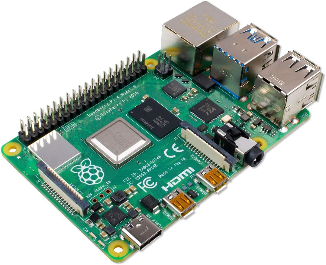
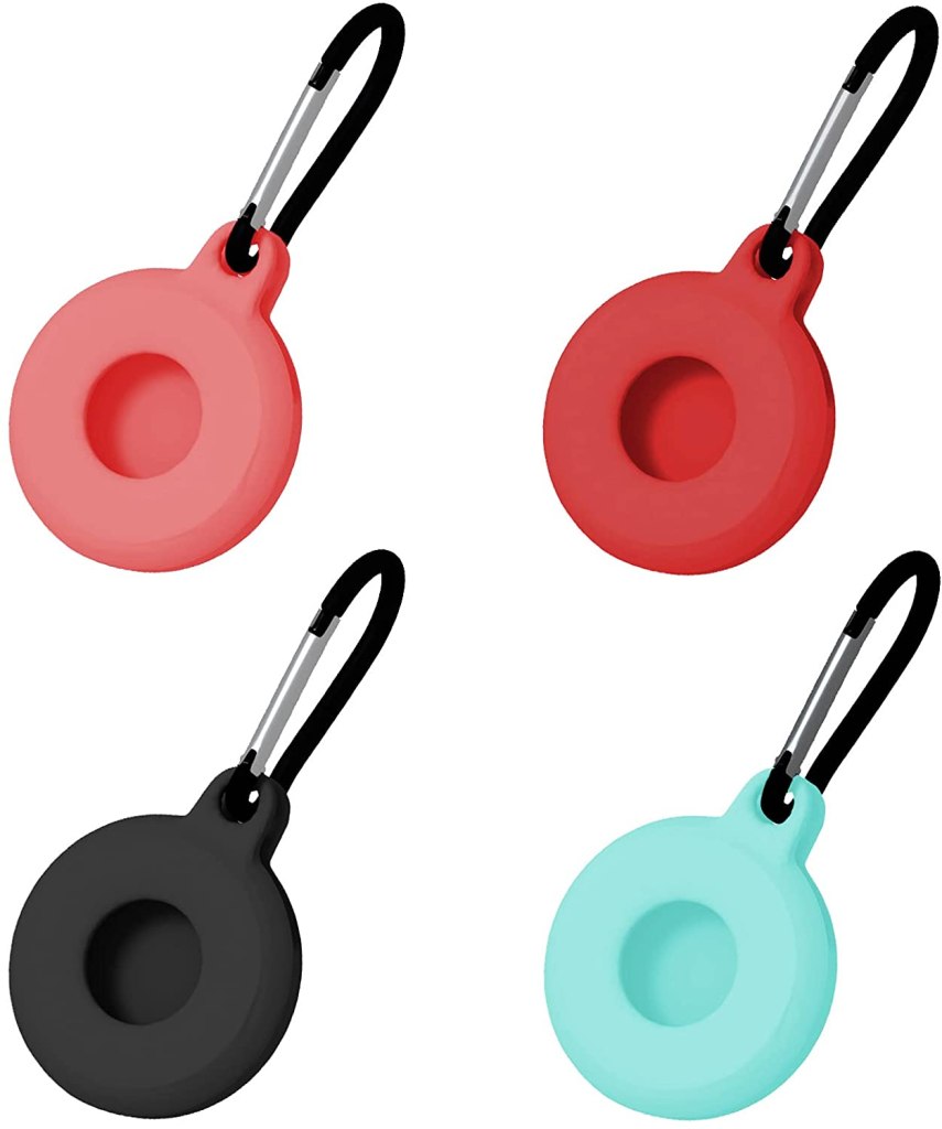
The code for the class I used for simulating the iBeacon follows. For the simplest use case, just instantiate the class and call the start() method. Provided the Info.plist has been populated with a value for NSBluetoothAlwaysUsageDescription and the user has granted permission, it should just work. In the next post, lets look at how to detect iBeacons with an iOS application. The next application isn’t limited to only detecting iPhones acting as iBeacons. It will work with real iBeacons too. As of now I have gotten my hands on a physical iBeacon compatible transmitter. While any iBeacon transmitter should work, if you would like to follow along with the same iBeacon that I am using, you can purchase the following from Amazon (affiliate link).

Posts may contain products with affiliate links. When you make purchases using these links, we receive a small commission at no extra cost to you. Thank you for your support.
Twitter: @j2inet
Instagram: @j2inet
Facebook: j2inet
YouTube: j2inet