Many apps require a network connection. Provided the connection meets bandwidth requirements, the apps don’t typically care how that connection is established. But for applications that engage in controlling home devices the application may specifically want to communicate over WiFi. In Android there are two ways that this has been handled. Some applications will turn on WiFi if it is turned off. Others may prompt the user to turn on WiFi.
Of the two options, the application turning on WiFi is an approach that is not supported on Android Q and later. This is part of the privacy changes in Android Q. For older versions of Android, controlling the WiFi could be performed though the WIFI_SERVICE.
val wifi = getSystemService(WIFI_SERVICE) as WifiManager
if(!wifi.isWifiEnabled)
    wifi.isWifiEnabled = true;
If you try this now, Android Studio will give a deprecation warning. To have the user change the WiFi state the application can open the WiFi control interface for the user. Rather than dump the user into the WiFi control interface, it is generally better to prompt them first. The WiFi control UI can be opened with an intent for ACTION_WIRELESS_SETTINGS.
An easy way to prompt the user is to use the AlertDialogBuilder. A complete solution looks like the following.
    fun checkWifiState() {
        val wifi = getSystemService(WIFI_SERVICE) as WifiManager
        if(!wifi.isWifiEnabled) {

            val dialogClickListener =
                DialogInterface.OnClickListener { dialog, which ->
                    when (which) {
                        DialogInterface.BUTTON_POSITIVE -> {
                            startActivity(Intent(Settings.ACTION_WIRELESS_SETTINGS));
                        }
                        DialogInterface.BUTTON_NEGATIVE -> {
                        }
                    }
                }

            var builder:AlertDialog.Builder = AlertDialog.Builder(this) as AlertDialog.Builder
            builder.setMessage("WiFi must be enabled. Do you want to open the WiFi controls?")
                .setPositiveButton("Yes", dialogClickListener)
                .setNegativeButton("No", dialogClickListener)
                .show()
        }
    }
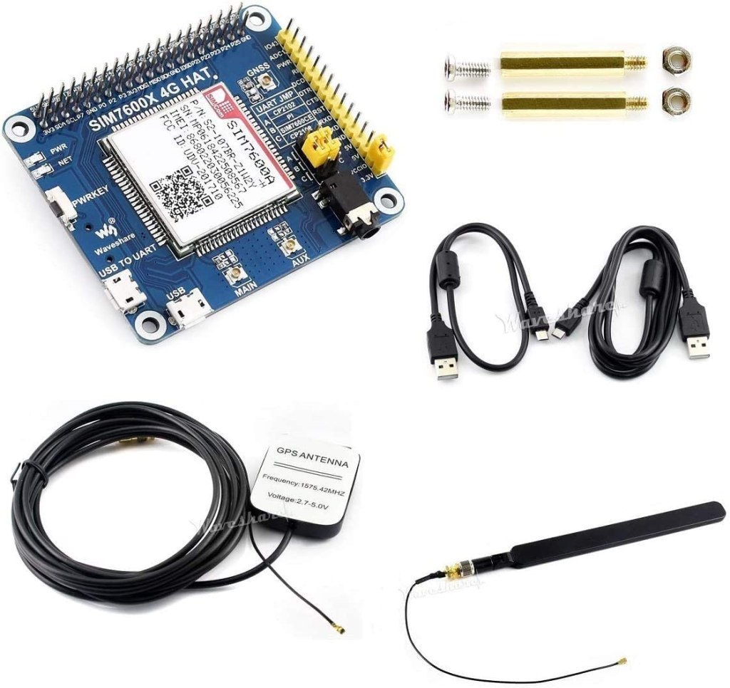
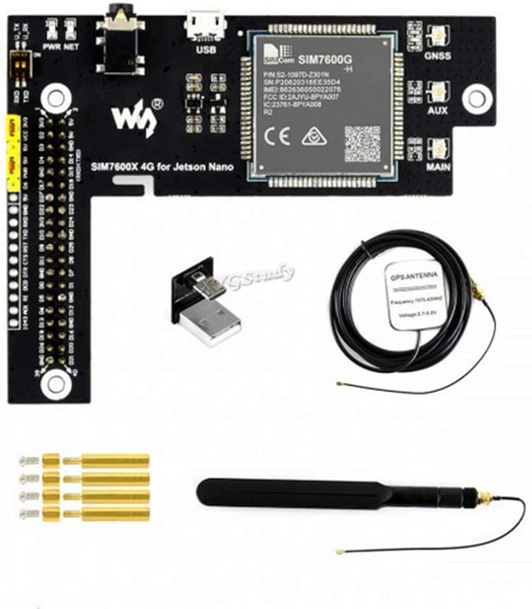
I’ve been using the Waveshare 7600 4G for the Jetson Nano (hereon referred to simply as the 7600). It gives the Jetson a connection for 4G mobile networks, GPS, and the ability to make and receive phone calls and SMS. (If you are looking for information on getting a WiFi connection see this post.) The Waveshare 7600 4G is a board built around the SIMCOM SIM7600X, an integrated circuit for providing communications functionality for a mobile phone. Waveshare makes variations of this device for both the Raspberry Pi and the Jetson Nano. While there is a wide amount of overlap in the usage of both devices, there are differences that are not immediately apparent from the top-level documentation. That said, reading documentation on one gives insight in using the other. The pin assignments used differ, but most of usage and functionality are the same.
When I initially looked at the Waveshare 7600 4G for the Jetson, there were elements of usage that didn’t make sense to me without consulting documentation from the chip maker and the schematic provided by Waveshare.
You don’t need to be familiar with the electrical schematic for the Waveshare board to use it. But if you would like more insight as to what the board is doing, continue reading.
SIMCOM 7600 Pinout
A quick glance of the pinout for the SIMCOM 7600 integrated circuit gives hints at a number of interfaces the chip supports. There are pins for power control, USB data transfer, interfacing to an SD card, GNSS, Flight mode, I2C, a UART interface, functionality concerning batteries, and analog to digital conversion. While the SIMCOM 7600 supports all of these interfaces, the Waveshare 7600 board built around this supports a subset of these interfaces; some of the lines on the SIMCOM 7600 are not connected to an external interface.
The schmatic that Waveshare provides is available on their Wiki at this URL. In the center of the schematic is the SIM7600.
SIM7600CX
Looking at this part of the diagram alone, you might notice that the pins labeled SCL and SDA are both tied to the positive voltage source instead of to other circuitry. These labels are associated with an I2C interface. Since the Waveshare’s board does not bridge the I2C pins between the Jetson Nano and the SIMCOM 760X, there is no I2C that you can use. Let’s take a look at how Waveshare’s device is connected to the Jetson Nano’s 40 pin header.
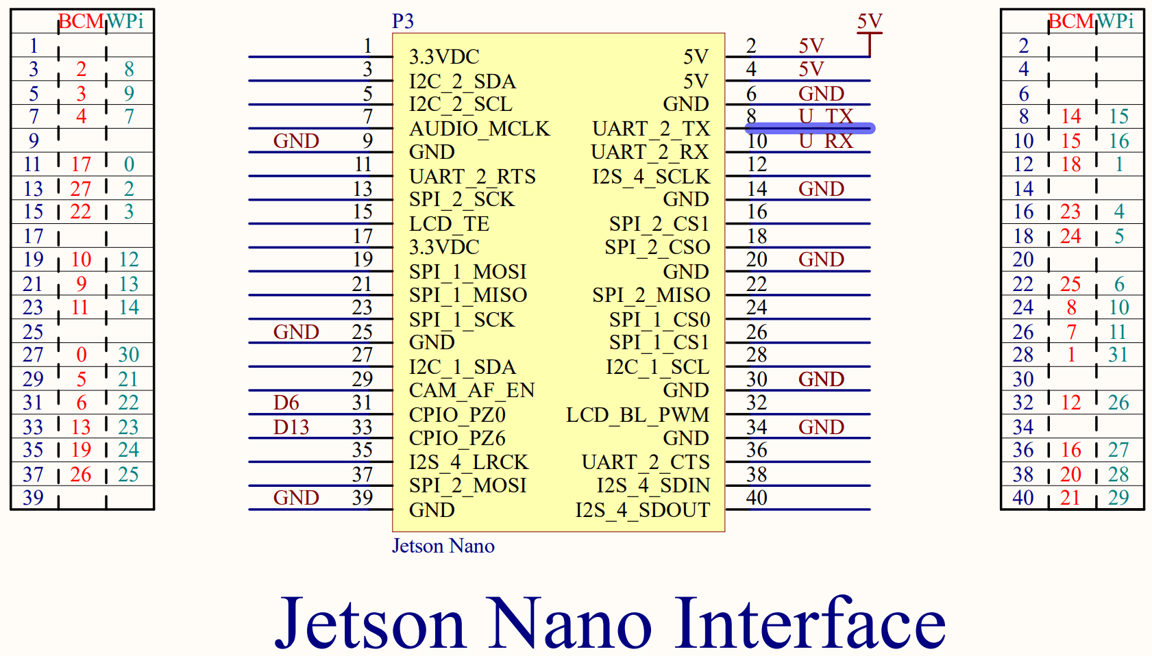
Waveshare Jetson Interface
Here you can see that the Waveshare board connects to some voltage and ground lines on the 40-pin interface. The only pins related to functionality used are pins 8 and 10 on the Jetson, which connect the Jetson’s UART to the SIMCOM 7600’s UART, and pins 31 and 33 on the Jetson, which connect to pins labeled D6 and D13 on the Waveshare board. Let’s trace these lines.
The two UART lines don’t connect directly to the SIMCOM 7600X. Instead they pass through a pair of switches and an integrated circuit identified as TXB0108EPWR. According to a datasheet (PDF), this circuit is a level shifter.
This circuit isn’t providing any additional signals. It allows the SIMCOM 7600, which uses 1.8 volt signaling, to communicate with the Jetson Nano over 3.3 volt signaling. The two switches allow the SIMCOM 7600’s UART and Jetson’s UART to be disconnected from each other. It is also possible to connect directly to the 3.3volt side of this circuit through pins exposed on the board.
Waveshare UART switch
There’s a schematic for the USB port. There’s nothing significant in the USB connection that you need to know. When I first got my hands on this board I was wondering why there were interfaces for both USB and a UART. Why are there two connections? This was answered by reading the SIMCOM 7600 documentation. The 7600 can accept AT commands over either interface and perform data transfers over either interface. The USB port is set to suspend if it is not used within some time period. It becomes active again during certain wake events.
In the Waveshare Wiki, developers are instructed to set a pin of the Jetson Nano to high and then low to ensure that the Wavesare device is turned on. The following is a script that can Waveshare provides for doing this.
There is not an explanation given as to what this is doing. GPIO200 is connected to pin 31 on the Jetson’s 40 pin header. Pin 31 leads to a pin labeled D6 on the board. What does pin D6 do? On the schematic we find that D6 terminates on a jumper.
D6 on Schematic
Layouts on an electrical schematic don’t necessarily map spatially. Looking at the physical connector in question, we can see more of what it does.
Closeup of D6
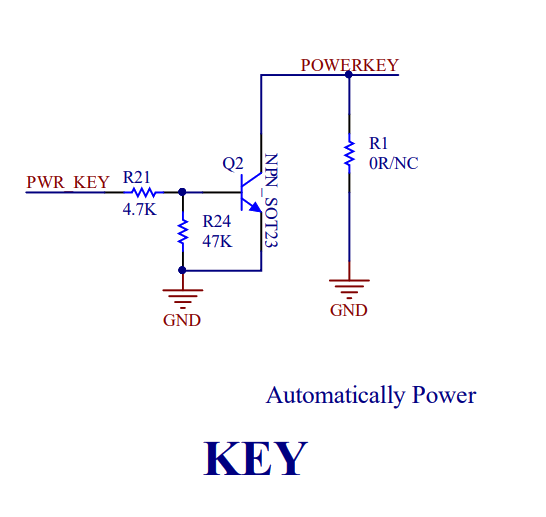
There is a jumper that can either bridge D6 to PWR, or bridge the 5V supply to power. In the above since PWR and 5V are connected, the PWR line will always be highm and pin 31 on the Jetson Nano is free for other purposes. If D6 and PWR are bridged, then the Jetson controls the power state of the board. The SIMCOM 7600 could go to a lower power mode for a number of reasons. This could include receiving a command instructing the SIMCOM 7600 to go to a lower power state. Pulsing this line will wake the SIMCOM 7600 up. If we look a little deeper at the schematic, we find PWR does not go directly to the SIMCOM 7600. It passes through another circuit.
Circuit for PWR signal
The end of the circuit labeled POWERKEY is connected to the SIMCOM 7600’s line of the same label. According to the SIMCOM 7600 documentation, connecting the power line to ground will power the unit on. (the POWERKEY line is connected to positive 1.8V internally within the SIMCOM 7600). The end result of this circuit could almost be viewed as being like an inverter; the high voltage from D6 or PWR results in the POWERKEY pin connecting to ground (low signal) and powering on. Sending a low signal to PWR causes the POWERKEY to be driven high by it’s internal resistor, which powers the SIMCOM 7600X off.
There is a circuit labeled “Flight Mode” that does something similar. The Flight Mode circuit bridges Pin 33 from the Jetson Nano to a pin on the SIMCOM 7600X labeled “Flight Mode.” As you may have inferred from using a phone, activating Flight Mode disables the radios within the SIMCOM 7600X.
Flight Mode circuit
There are a few other components on the schematic that don’t involve any signaling with the Jetson Nano. Of course, there is also the circuit that connects to the SIM card. Waveshare has also supplied a circuit for interfacing with earphones and a microphone. To use this feature you only need to connect a headset to the jack on the board.
There are three more interfaces on the schematic for the antennas. Two of these antennas are self-explanatory. The GNSS connector for a GPS antenna. The Main connector for a cellular antenna. There is a third antenna that is labeled as AUX on the Waveshare board, and DIV Ant on the schematic. While not strictly necessary, connecting an antenna to this connector can enhance the 4G performance of the SIM 7600.
That covers all of the circuits that connect to the Waveshare 7600X 4G.
Posts may contain products with affiliate links. When you make purchases using these links, we receive a small commission at no extra cost to you. Thank you for your support.
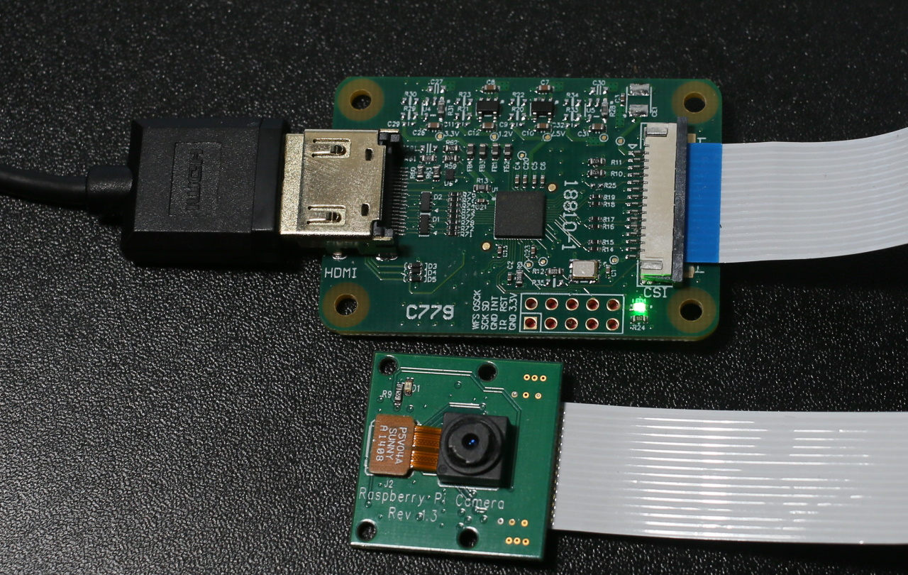
Back in January I tweeted about an HDMI capture device that for the Raspberry Pi. I’ve only recently have gotten a chance to use it. The device, known as the “HDMI to CSI-2 module”, works with the Raspberry Pi. Overall my experience was positive, though I found that this device has limitations that, if not previously known, can result in some frustration. The device connects to the CSI-2 camera interface and presents itself as a camera. The utilities and scripts that you may have used with the Raspberry Pi also work with this device without modifications. Along with the HDMI capture module the package contains the cable needed for connecting it to the full size Raspberry Pi and a second cable for use with a Raspberry Pi Zero.
One of the first uses that came to mind with this device is that I could use camera options beyond the official Pi cameras. The camera that I have about the house produce clean HDMI signals. They already have a range of lenses, ranging from some macro lenses for pictures of small items close-up and a 2132 millimeter Schmidt–Cassegrain for astrophotography.
My smallest lens next to my largest lens. Both of which are not available for use on the Pi through my digital camera.
The first time I tried to use the capture device with one of my cameras, it didn’t work. I received a non-descriptive error that is primarily associated with non-working or improperly installed cameras.
mmal: mmal_vc_component_enabled: failed to enable component: ENOSPC
mmal: camera component couldn't be enabled
mmal: main: Failed to create camera component
mmal: Failed to run camera app. Please check for firmware updates
Thankfully, this isn’t indicative of an actual hardware failure. The capture device works with a limited set of resolutions and refresh rates. For 1080p video signals, the maximum refresh rate is 25 fps.
Resolution
Refresh Rate (fps)
720p
50
720
60
1080i
50
1080p
24
1080p
25
Supported Resolutions
After making adjustments to the output settings of my camera, I was successful in using it with the HDMI capture.
The camera was the first device that came to mind, but it could work with non-camera HDMI sources too. I connected a Nintendo Switch to the device and it captured from the switch just fine. Provided that the signal is within the resolution and FPS range and is not an encrypted (HDCP) signal, it works.
Comparing the HDMI capture device to the Raspberry Pi cameras, there were a few differences to note. While it may be easy to assume that the digital photo camera paired with this device is better than the Raspberry Pi cameras, that isn’t necessarily the case. “Better” is a matter of what satisfies the requirements for a solution. If that solution requires high physical portability, the photo camera’s size could be a disadvantage. Using an external camera also ads to external power needs; the external camera will need to have it’s own battery or power supply. The official Raspberry Pi cameras run off of the Raspberry Pi’s power.
HDMI to CSI-2 Module next to Raspberry Pi Camera
The Pi cameras offer some higher resolutions than one can capture with the HDMI capture device. Resolution is an attribute of quality, but not the only metric for quality. I hesitate to label the higher resolution as higher quality because there are cases where a lower resolution camera may be rated better on other quality metrics, such as clarity or dynamic range, or may have attributes that make it a better fit for a specific application, such as a different shutter angle.
The Raspberry Pi HQ camera (recognizable from it’s C-mount for attaching a lens) can capture still photographs of up to 4056×3040 pixels. The Raspberry Pi Camera v2 captures stills at up to 3280×2464 pixels. For video, all of the cameras have the same resolution. Keep in mind though at these higher resolutions since the device is receiving stills and not video frame the rate of capture will be much lower.
Resolution
Frame Rate (fps)
1080p
30
720p
60
4809
60/90
Raspberry Pi Camera Framerates
How did it work? After trying it on a Raspberry Pi with a Nintendo Switch I would rate the capture device as being okay. It isn’t stellar, but it isn’t bad either. It provides a way to interface with HDMI sources. During the process of recording, it appeared there were frames that were dropped. The playback confirmed this. I was wondering if the dropped frames were due to the speed of the memory card in the Pi or from some computational limits on its ability to encode the video to .H264. The next thought that came to mind was to try it with the Jetson Nano. Sadly, while the Jetson Nano uses the CSI-2 interface, at the time of this writing it is not compatible with the Jetson Nano.
Registration for Nvidia’s GPU Technology Conference (GTC) is now open at no cost. From April 12 to April 16, Nvidia will be offering online presentations with an emphasis on AI applications. The presentations go into the industries of healthcare, networking, game development, robotics, and more. Over 1,600 sessions are listed in the session catalog. Much like last years conference, this conference will be going around the clock. Don’t be surprised if you see a session scheduled for 3:00AM or 10:00PM. If you don’t manage to catch a presentation live you can watch a presentation later once the recording is posted.
Posts may contain products with affiliate links. When you make purchases using these links, we receive a small commission at no extra cost to you. Thank you for your support.
Android Instant Apps offer a way for users to try out your application without fully installing them. An instant app can be launched from a link. A link on a website could launch your Instant App without the user needing to check to ensure that they have the application installed first. This allows someone to experience the intended experience in only a few moments. I’m very much a proponent of Instant Apps since they potentially make it less necessary to review what apps have not been used in a while as candidates for removal to manage the storage on a device; if a system becomes low on resources, the device will removed the cached instant apps as needed. If an application is Instant App enabled, the Play Store will present both a “Try Now” and “Install” button
If an application is made of several modules, only the modules needed for the instant app to run are downloaded. This is enabled through AABs(Android Application Bundle). Later this year, in August 2021, Android apps published through Google Play must be packaged as AAB instead of an APK. A key difference in the AAB and APK is that the AAB contains the binaries and files for all variants of your application (ARM, ARM64, x86) and the layouts. Google Play will then use dynamic delivery to ensure that the components that a specific device needs are delivered to that device.
Since only the components that are needed are downloaded, the user does not have to wait on the entire application package to download for the application to open. This process is faster than downloading and installing regular applications; it is perceivably instant in some cases. Instant applications must be limited to 15 MB in size.
To use the Instant App feature, your application must support Android 5.0 at minimum. Though after November 2021 developers will be required to target Android 11. No, this doesn’t mean that support is dropped for people with older phones. An Android application’s build.gradle has both a targetSdkVersion attribute and a minimumSdkVersion attribute. The minimum version can be lower than the target version. Android 8.0 (API target 26) and higher provides some advantages when a user moves from using the Instant app to installing the application. If the user decides to install the application, this is considered an upgrade. The data that the application has stored on the user’s device will migrate to the full application. For API 25 and before the data transfer is not automatic. The Storage API will need to be used to transfer the data manually.
For much of the documentation that is available today it is suggested that when creating your Instant App that you ensure a check box is checked at the time of the application creation. Looking in Android Studio today this frequently mentioned checkbox does not exists. If you encounter this, you may be looking at documentation based on older versions of Android Studio.
In Android Studio you will want to ensure the Instant App SDK is installed. In the SDK Manager you will find it under the “SDK Tools” tab. The item is titled “Google Play Instant Development SDK.”
Create an Android application. To enable the instant app feature, a few modifications are needed. You can make these modifications manually or through a menu option. To make the change through the menu option right-click on your app’s module, select “Refactor” and then “Enable Instant Apps Support…”
Selecting this menu option makes changes to your application’s Manifest and the App level build.gradle. In AndroidManifest.xml, a new namespace is added to the root element. An item specifying a sandbox version is also added to the element.
An additional element is added to the manifest named <dist:module /> with an attribute dist:instant set to true. You can add an optional dist:title attribute with a string that may be presented to the user to identify your application.
While this enable’s an application for instant launch, there are other considerations that you will want to make for the best experience. This includes potentially dividing your application into modules to put the most essential features that will be available in the Instant app in a smaller module for quick launch while the other features of your application are in another module. Presently, instant apps are limited to 15 megabytes. One strategy may be having activities for viewing data in a module (so that user’s can view data that your application’s services offer) with some light-weight editors and placing a more capable editor and other application features in a different module.
There are several ways to test your Instant App. One way is through the Google Play development console. You have the option of your Instant app and the full install as being the same or separate applications. If they are separate, they don’t even need to be in the same project. They do need to use the same package name. If you decided for them to be different projects, then their version numbers must be different. The Instant App needs to have a lower version number than the full application. The transition from the instant app to the full app, should the user decide to perform an install, is treated as an upgrade.
Within the console, upload your full application as you normally would within the choses testing track. After it is uploaded, select your application from the console and select “Advance settings.” Under the tabs, select “Release Types” and then select the button to add a new release type. “Google Play Instant” is the type that you want to add.
In the development console select the option to make a new release. You will now have a drop-down where you can select the release type. Select “Google Play Instant.”
You will be prompted to select or upload an application package. If your instant application is the same as your full application, here you can select the previously uploaded AAB. Otherwise, upload the instant version of the application. After filling in the information for the release, you are done, but possibly not ready to test.
When I uploaded my first instant app, the process was a bit frustrated by not knowing that the Instant App isn’t necessarily available in the Google Play Store instantly. For me, the full application showed, but the Instant app was nowhere to be found. It can take a day (and sometimes longer) for the option to try the application to show up. Have a bit of patience here. The instant version of your application will (ironically) become available with time.
Posts may contain products with affiliate links. When you make purchases using these links, we receive a small commission at no extra cost to you. Thank you for your support.
I’m testing some code that accepts some work items and performs a long running task on the work items. For this project, I generally want the screen to be locked since I’m going to be away from the computer for some time while it runs. I recently decided to make locking the screen part of the script that invokes the tasks. Yes, I could just press [Windows Key]+[L], but if there’s something that I’m doing repeatedly, I would prefer to just automate it and not worry about it.
Locking the screen from a program is easy. Making a call to the parameter-less function LockWorkStation* results is what I want. I thought I would just make a simple C++ program that does nothing more than make this call and be done with it. But something about that didn’t feel right; why make an entire program to invoke that single problem. It actually isn’t necessary to make a program to do this. Windows has a utility in the System32 folder. RunDll32.exe. The utility is specifically made for calling functions in DLLs that were written to process Windows message. If you have ever done Windows 32 programming with C++ then you are already familiar with these. Calling functions with no parameters is fine also
In the general case, Rundll32.exe accepts the name of the DLL to invoke and the name of the function within the DLL. For my need, the call looks like the following.
Rundll32.exe user32.dll,LockWorkStation
Win32 functions generally have the following call signature.
RunDLL32 will take care of converting arguments from strings on the command line to the data types being passed. Be careful about using this utility; if you pass bad values, expect bad results. For the following, I passed the name of an HTML file from the command prompt and a print dialog opened for printing it out.
rundll32 mshtml.dll,PrintHTML "A title for my document", "C:\temp\map.html"
While I find this to be a useful utility, I don’t recommend it for anyone that isn’t already familiar with calling Win32 functions.
* – the command tsdiscon has a similar affect. It disconnects the current session from the graphical desktop. But when I use this command logging back in takes much longer and I prefer not to use it.
After some holiday time off I returned to a work project that uses Angular, started it up, and got this error.
An unhandled exception occurred: listen EACCES: permission denied 127.0.0.1:443
I’ve seen this error before, but did not immediately realized what caused it. It took me a few minutes to recall the source of the problem. This error occurs when there is another application that is already using the port that Angular is trying to open. In my case, it was a VMWare service that was occupying the port. I stopped the service and my project started up. If it happened to you, how would you know what process is using the port?
On Windows, you can list which processes are using which port with the following command
netstat -aon
You’ll get a full list of ports, addresses, and process IDs.
If you wanted to filter those results, you can pass the output through “findstr” using a port number as the string to filter by.
C:\Users\Joel>netstat -aon | findstr 443
   TCP    0.0.0.0:443            0.0.0.0:0              LISTENING       38880
   TCP    0.0.0.0:44367          0.0.0.0:0              LISTENING       4
   TCP    192.168.1.81:49166     72.21.81.200:443       TIME_WAIT       0
   TCP    192.168.1.81:49169     64.233.177.101:443     TIME_WAIT       0
   TCP    192.168.1.81:49206     13.249.111.97:443      ESTABLISHED     24324
   TCP    192.168.1.81:49209     52.167.253.237:443     ESTABLISHED     1996
   TCP    192.168.1.81:49220     52.184.216.246:443     ESTABLISHED     37976
   TCP    192.168.1.81:49222     168.62.57.154:443      ESTABLISHED     24324
   TCP    192.168.1.81:49224     52.114.74.45:443       ESTABLISHED     13304
   TCP    192.168.1.81:49227     52.113.194.132:443     ESTABLISHED     10376
   TCP    192.168.1.81:49228     184.24.37.85:443       ESTABLISHED     27828
   TCP    192.168.1.81:49231     13.92.225.245:443      ESTABLISHED     27828
   TCP    192.168.1.81:49233     140.82.113.3:443       ESTABLISHED     24324
   TCP    192.168.1.81:49234     20.190.133.75:443      ESTABLISHED     39168
   TCP    192.168.1.81:49236     204.79.197.203:443     ESTABLISHED     27828
   TCP    192.168.1.81:49238     52.96.104.18:443       ESTABLISHED     12440
   TCP    192.168.1.81:49239     52.96.104.18:443       ESTABLISHED     12440
You will be more interested in matches from the left column, since that is the port number being used on your machine. Right now, I can see that on my machine the process occupying port 443 is process 38,880. Great, I have a process number. But what can I do with it. There is another command named “tasklist” that list processes names and their process ID. Combined with findstr, I can get the name of the process using the specific port.
C:\Users\Joel>tasklist | findstr 38880
 vmware-hostd.exe             38880 Services                   0     32,084 K
I’ve got a range of media that I’m moving from its original storage to hard drives. Among this media are some DVDs that I’ve collected over time. It took a while, but I managed to convert the collection of movies and TV shows to video files on my hard drive. Now that they are converted, I wanted to build a solution for browsing and playing them. I tried using a drive with DLNA built in, but the DLNA clients I have appear to have been built with a smaller collection of videos in mind. They present an alphabetical list of the video files. Not the way I want to navigate.
I decided to instead make my own solution. To start though, I wanted to make a solution that would stream a file video file. Unlike most HTML resources, which are relatively small, video files can be several gigabytes. Rather than have the web server present the file in its entirety I need for the web server to present the file in chunks. My starting point is a simple NodeJS project that is presenting HTML pages through Express.
With the above application, static content any files that are put in the folder named “public” will be served when requested. In that folder, the stylesheet, JavaScript, HTML, and other static content will be placed. The videos will be in another folder that is not part of the project. The path to this folder is specified by the setting VIDEO_ROOT in the .env file.
For this to stream files, there are two additional routes that I am going to add. One route will return a list of all of the video IDs. The other route will return the video itself.
For this first iteration for video streaming, I’m going to return file names as video IDs. At some point during the development of my solution this may change. But for testing streaming the file name is sufficient. The route handler for the library will get a list of the files and return it in a structure that is marked with a date. The files it returns are filtered to only include those with an .mp4 extension.
The video element in an HTML page will download a video in chunks (if the server supports range headers). The video element sends a request with a header stating the byte range being requested. In the response, the header will also state the byte range that is being sent. Our express application must read the range headers and parse out the range being request. The range header will contain a starting byte offset and may or may not contain an ending byte offset. The value in the content range may look something like the following.
byte=0-270 byte=500-
In the first example, there is a starting and ending byte range. In the second, the request only specifies a starting byte. It is up to the server to decide how many bytes to send. This header is easily parsed with a couple of String.split operations and integer parsing.
function getByteRange(rangeHeader) {
    var byteRangeString = rangeHeader.split('=')[1];
    byteParts = byteRangeString.split('-');
    var range = [];
    range.push(Number.parseInt(byteParts[0]));
    if(byteParts[1].length == 0 ) {
        range.push(null);
    } else {
        range.push(Number.parseInt(byteParts[1]))
    }
    return range;
}
There is the possibility that the second number in the range is not there, or is present but is outside of the range of bytes for the file. To handle this, there’s a default chunk size defined that will be used when the byte range is not specified. But the range is also checked against the file size and clamped to ensure that there is no attempt to read past the end of the file.
const CHUNK_SIZE = 2 ** 18;
//...
var start = range[0];
if(range[1]==null)
    range[1] = Math.min(fileSize, start+CHUNK_SIZE);
var end = range[1] ;
end = Math.min(end, fileSize);
In the response, the header contains a header defining the range of bytes in the response and it’s length. We build out those headers, set them on the response header, and then write the range of bytes. To write out the bytes, a read stream from the video file and piped to the response stream.
The server can now serve video files for streaming. For the client side, some HTML and JavaScript is needed. The HTML contains a video element and a <div/> element that will be populated with a list of the videos.
The JavaScript will request a list of the videos from the /library route. For each video file, it will create a text element containing the name of the video. Clicking on the text will set the src element on the video.
function start() {
    fetch('/library')
    .then(data=>data.json())
    .then(data=> {
        console.log(data);
        var elementRoot = $('#videoBrowser');
        data.fileList.forEach(x=>{
            var videoElement = $(`<div>${x}</div>`);
            $(elementRoot).append(videoElement);
            $(videoElement).click(()=>{
                var videoURL = `/video/${x}`;
                console.log(videoURL);
                $('#videoPlayer').attr('src', videoURL );
            })
        });

    });
}

$(document).ready(start());
Almost done! The only thing missing is adding these routes to the source of app.js. As it stands now, app.js will only serve static HTML file.
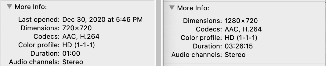
I started the application (npm start) and at first, I thought that the application was not working. The problem was in the encoding of the first MP4 file that I tried. There are a range of different video encoding options that one can use for MP4 files. Looking at the encoding properties of two MP4 files (one file streamed successfully, the other did not) there was no obvious difference at first.
The problem was with metadata stored in the file. A discussion of video encodings is a topic that could be several posts of its own. But the short explanation is that we need to ensure that the metadata is at the begining of the file. We can use ffmpeg to write a new file. Unlike the process of re-encoding a file, for this process the video data is untouched. I used the tool on a movie and it completed within a few seconds.
Whether you are developing for a consumer Samsung TV or for one of the commercial SSSP displays you’ll need to have a development certificate for your code to run. There is a difference in how the certificate is created for the commercial and consumer displays. But the process is similar off the same for both.
To get started you’ll need to already have Tizen Studio installed. Open the Tizen Studio package manager and make sure that you have the following components installed.
Samsung Certificate Extensions
If you don’t already have the component installed select it for installation. You’ll also need to have the SDK component installed for the version of Tizen that you are targeting (ex: “5.0 TV”). Once the component is present start the Tizen Studio Device Manager.
The device manager will be used to get the device’s ID (DUID) for consumer TVs and for installing the development certificate onto the display. For these steps to work the TV must have development mode enabled and must be set to accept development requests from the same IP address as your development machine; it will refuse request from other addresses. If you haven’t already enabled development mode I have another posts on how to do that here
.
In the device manager there is an icon in the upper right corner of a phone connected a computer. Select this icon. It is for establishing connections to the device manager. In the window that opens you will see a list of devices that you’ve previously connect to. If the IP address of your display is there you can click on the icon of the on/off switch to reconnect to it. If the IP address of your display is not present click on the + icon to add it. When adding you can give the TV a descriptive name, enter the IP address, and the port on which to connect (usually 26101). Click on OK to return to the main Device Manager user interface and you should see your display connected. Right-click on the display and select DUID to see the ID of the display. Go ahead and copy it to the clipboard. You will need it in later on. If you have multiple displays for which you will develop repeat the same steps to collect the DUID values for the other displays and save them to a text document. Note that if you have both consumer and commercial displays that the DUIDs for them cannot be used mixed with each other. You can perform the following steps for all of your consumer displays at once and then all of your commercial displays at once.
Open the Certificate Manager. When it is opened for the first time you may be asked to select a location from which you want to import certificate profiles. Select Cancel here. You will need to create both an Author certificate and a Distributor certificate. Click on the + icon in the upper right corner to start the process of creating a new certificate. What you select on the window that appears is dependent on the type of display for which you are developing.
Commercial (SSSP) Display Steps
For the commercial displays select “Tizen. ” In the next step you’ll be asked to enter a name for the certificate profile. If you develop for other device types (such as the mobile device, watch, or the consumer displays) you’ll need to have more than one certificate profile. It will be good for them to have easily identifiable names. Enter a name here that let’s you know that this is a certificate for developing for a commercial display and select Next.
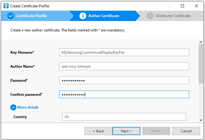
Next you must select an author certificate. If you’ve created an author certificate before you have the option to select it. If not then select the option to create a new one. I’ll assume that an author certificate has not been created yet. The minimal amount of information that you need for an author certificate is a name, a password for the certificate (don’t forget this password!). You can optionally enter your country code, State, City, Organization, department, and an e-mail address and a filename in which the key file for the certificate will be saved. Enter your options and select “Next”
The last selection to make is whether you want to use the default Tizen distributer certificate . While this selection will allow you to submit mobile applications to the Tizen store it is fine for our purposes. Select it and click on “Finish.” With this you have a
Consumer Display Steps
For the consumer displays when asked for the certificate type select “Samsung”.
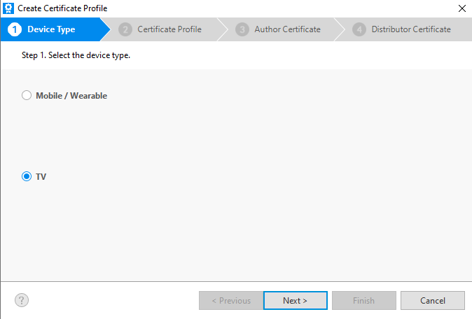
On the next screen you’ll be asked for the device type. Select “TV.”
Enter a name for the profile and select next.
Next you’ll select an author certificate. If you already have an author certificate that you’d like to use you can select it here. If you would like to create a new certificate (which you would do if you’ve never created one before) select the first option. You would also select this option if you had a certificate but it has expired. If you had a certificate that has expired you may want to select the option to create a new certificate and check the box that says “Use an Existing Certificate.” If you have an application that has been published to the Tizen store before and are creating a new certificate then you’ll want to use this option since an application’s ID is in part based on the certificate with which it was signed.
Enter the your author information. Remember what your password is, especially if you plan to publish your application under this certificate. When you click on “Next” you’ll be asked to sign into your Samsung account. After signing in your Author certificate is created.
You’ll be presented with the option of backing up your certificate. While this isn’t required it is strongly encouraged. You will want to keep this secure as it forms part of the identity for your apps. But you are almost done. You need a distributor certificate
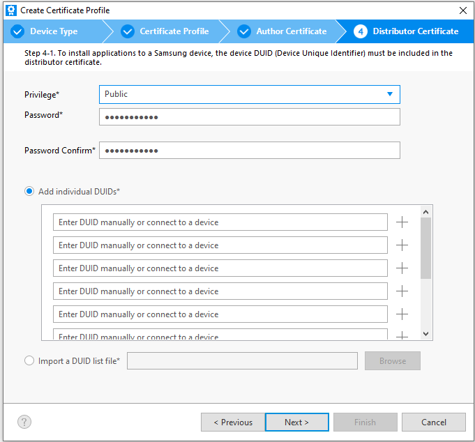
On the next screen you are prompted to either create a new distributor certificate or select an existing one. Choose the option to create a new one.
Now it is time to use the DUID that you copied earlier. If it is already on your clipboard it will automatically be pasted into one of the entries for DUID. You also have the option to change the privilege level, but not really. The two privileges available are “Public” and “Partner.” Partner gives you application to functionality that isn’t available to everyone. But to use Partner level privileges they have to be granted to you by Samsung.
After you click on “Next” you’ll be greeted with a confirmation that the certificate has been created along with the path to the certificate being shown.
For Both Consumer and Commercial
Now that your certificates have been created you need to let the display know about it so that it can recognize applications that were signed with your certificate and allow them to run. To do this return to the device manager. Right-click on the your display in the device manager and select “Permit to install apps.” The display is ready to accept applications now.
Switching Certificate Profiles
If you are developing for more than one type of Tizen device you’ll probably have to change which certificate profile that you are using as you change which platform you are working on. When you need to change profile open the certificate manager. You will see a list of the profiles that you’ve set up and a check-mark next to one marking it as the active profile. If you want to change which profile is active select it from the list and click on the check mark in the upper right corner.
With the certificate created and selected you can now move forward with deploying an application to the display. Start off with a hello world program just to see that it works.
If you’ve followed the directions for writing the OS for the nano you are mostly setup for development. The tools that you must have are already part of the image. But you’ll want to have a code editor. I chose to use Visual Studio Code on the Nano. While Microosft doesn’t distribute the binary themselves it can be compiled for the ARMs processor. But I was able to follow the three step instructions available from code.headmelted.com. To summarize the steps here
A few minutes later visual studio code will be installed and available.
I’m using MAKE file for my project. But the first thing I needed to figure out was what compiler should I use and where on the file system is it. The CUDA compatible file system of choice is nvcc. It can be found at the following path.
/usr/local/cuda/bin/nvcc
To make sure it worked I made a simple hello world program and saved it using the totally wrong file name of helloWorld.cpp. I say “wrong” because the compiler looks at the file extension and treats the file differently based on that extension. Instead of using cpp I should have used cu. With CPP the compiler doesn’t understand the directives for the CUDA code.
__global__ void cuda_hello()
{
    printf("Hello World from GPU!\n");
}

using namespace std;

int main()
{
        cout << "Hello world!" << endl;
        cuda_hello<<<1,1>>>();
        return 0;
}
To compile the code I use the following at the command line.
I’ve been taking advantage of Web Assembly lately. It is supported by all the major browsers, let’s one make use of already existing useful code that has been written for other environments, and provides some performance benefits over JavaScript. Web Assembly has a lot of potential and support and I’d like to introduce other developers to it. I’m going to be using C++ in this post. But by no means is this the only language in which someone can make use of Web Assembly. In this post I talk about why someone might want to consider web assembly and how to get a development environment setup.
What is Web Assembly?
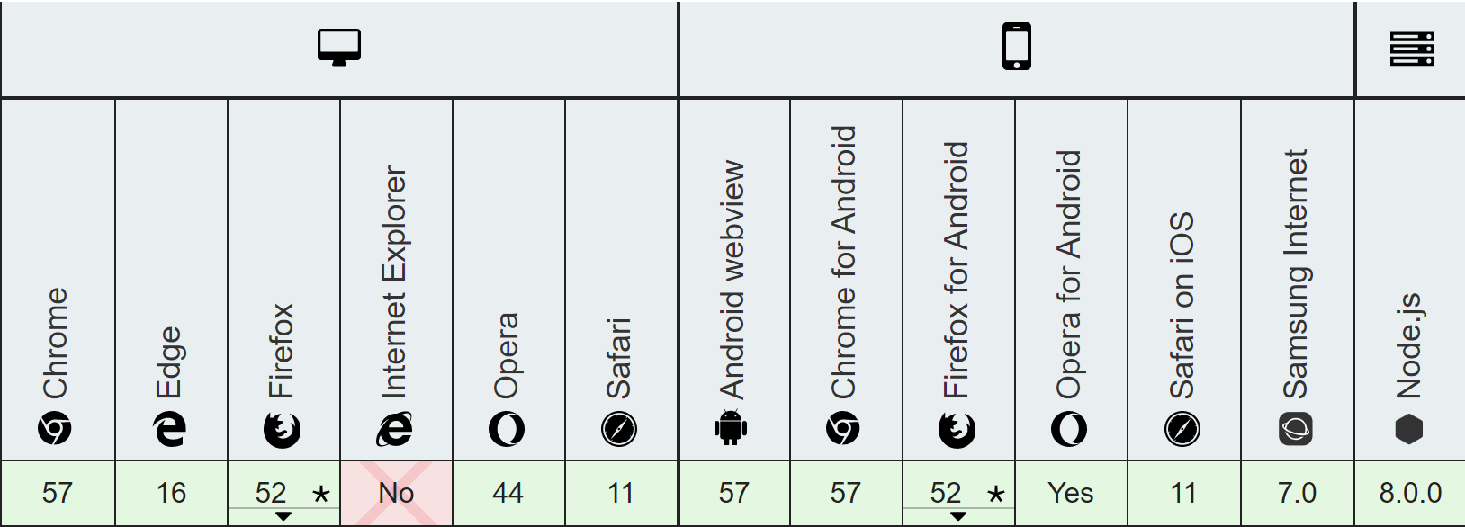
Web Assembly is a specification for a virtual machine that runs in the browser. Compared the the highly dynamic JavaScript Web Assembly can achieve much higher performance. Contrary to popular misconception though Web Assembly doesn’t completely replace JavaScript. You will probably use the two together. Web Assembly is based on LLVM (Low Level Virtual Machine), a stack based virtual machine that compilers can target. If someone wanted to make a new programming language they could have the compiler for their language produce LLVM code and then use an already existing tool chain to compile it to platform specific code. A person building a compiler for a new language wouldn’t need to make completely separate systems for different CPU architectures. Web Assembly being LLVM based could run code that was written by a variety of languages. Currently there isn’t support for garbage collection yet which restricts the languages that target it presently. C/C++, C#, and Rust are a few languages that can be used with Web Assembly presently with more expected in the future.
What Other Languages Can I Use?
C/C++ – I’ll be using that language in this article
C#/.Net – I’ve got interest in this one and will write about it in the future.
I suggest Web Assembly primarily for the performance benefits in computationally expensive operations. The binary format it uses is much more strict than JavaScript and it is more suitable for computationally intensive operations. There is also a lot of existing and tested code for work such as cryptography or video decoders that exists in C/C++ that one might want to use in a page. Despite all its flexibility interpreted JavaScript code doesn’t run as fast as a native binary. For some types of applications this difference in performance isn’t important (such as in a word processor). For other applications differences in performance translate into differences in experiences.
While the demand for performance is a motivation to make a native binary there are also security considerations. Native binaries may have access to more system resources than a web implemented solution. There may be more concern with ensuring that a program (especially if it is from a third party) doesn’t do anything malicious or access resources without permission. Web Assembly helps bridge the gap between these two needs; it provides a higher performance execution environment within a sandbox.
C++? Can’t I Cause a Buffer Overflow With That?
Sure. But only within the confines of the sandbox in which the code will run. It could crash your program, but it can’t cause arbitrary execution of code outside the sandbox. Also note that presently Web Assembly doesn’t have any bindings to Host APIs. When you target Web Assembly you don’t have an environment that allows you to bypass the security restrictions in which JavaScript code will run. There’s no direct access to the file system, there’s not access to memory outside of your program, you will still be restricted to communicating with WebSockets and HTTP request that don’t violate CORS restrictions.
How Do I Setup a Developer Environment
There are different versions of instructions on the Internet for installing the Web Assembly tools. If you are running Windows 10 you may come across a set of instructions that start with telling you to install the Windows Subsystem for Linux. Don’t use those instructions; I personally think they are unnecessarily complex. While I have the Windows Sub System for Linux installed and running for other purposes that’s not where I like to compile my Web Assembly code.
Using your operating system of choice (Windows 10/8/7, macOS, Linux) clone the Emscripten git repository, run a few scripts from it, and you are ready to go. Here are the commands to use. If you are on Windows omit the ./ at the beginning of the commands.
With the tools installed you will also want to set the some environment variables. There is a script for doing this. On Windows 10 run
emsdk_env.bat
For the other operating systems run
source emsdk_env.sh
The updates that this makes to environment variables isn’t persistent; it will need to be run again with the next reboot. For an editor I suggest using Visual Studio Code. I’ll be compiling from the command line in this article. Feel free to use the editor of your choice.
Web Assembly Explorer
I don’t use it in this tool within this article, but Web Assembly Explorer is available as an online tool for compiling C++ into Web Assembly and is an option if you don’t have the tools installed.
Now that we have the tools installed we can compile and run something. We will do a hello world program. Type the following source code and save it in hello.cpp.
To compile the code from the command line type the following.
emcc hello.cpp -o hello.html
After the compiler runs you will have three new files.
hello.wasm – the compiled version of your program
hello.html – an HTML page for hosting your web assembly
hello.js – JavaScript for loading your web assembly into the page
If you try to open the HTML file directly your code probably will not run. Instead the page will have to be served through an HTTP server. If you have node installed use the node http-server. You can install the http-server with
npm install http-server -g
Then start the server from the directory with your hello.html
http-server . -p 81
Here I’ve instructed the http-server to run on port 81. You can use the port of your choice here provided nothing else is using it. Remember to substitute the port that you chose throughout the rest of these instructions.
Open a browser and navigate to http://localhost:81/hello.html. You’ll see your code run. If you view the source for the page there is a lot of “noise” in the file. Much of that noise is from the displayed images being embedded within the HTML. That’s fine for playing around. But you will want to have something customized to your own needs.
We can provide a shell or template file for the compiler to use. Emscripten has a minimal file available at https://github.com/emscripten-core/emscripten/blob/master/src/shell_minimal.html. Download that file. It will be used as our starting point. It is convenient for the sake of distribution for everything to be in one file. But I don’t like the CSS and JavaScript being embedded within the file. The CSS here isn’t needed and is being deleted. I’m moving the JavaScript to its own file and added a script references to it in my HTML. There are several items within the HTML and the script that are not necessarily needed. Let’s look at the script first and start making this minimal file even more minimalist.
At the top of the script there are three variables to page elements to indicate download and progress. Those are not absolutely necessary. I’m deleting them. I need to delete references to them too. Lower in the JavaScript is a method named setStatus . I’m replacing it’s body with a call to console.log() to print the text that is passed to it. The first set of programs that I’m going to write won’t use a canvas. The element isn’t needed for now; I’m commenting it out instead of deleting it so that I can use it later. Having deleted the first three lines of this file and and code that references them I’m returning to the HTML. Most of it is being deleted. I’ve commented out the canvas reference. There is a line in the HTML file with the text {{{ SCRIPT }}}. The compiler will take this file as a template and replace {{{ SCRIPT }}} with the reference to the script specific to our Web Assembly file.
When the Web Assembly program executes a printf() the text will be written to the textarea element. I place my hello.cpp file among these files and then compile it with the following command.
The –shell-file argument indicates what file to use as a template. The -o parameter tells the name of the HTML file to write to. If you look at hello.html you can see it is almost identical to the input template. Run the site now and you’ll see the same result, but with a much cleaner interface. Run the program again and you will see the same result with a much cleaner interface.
Binding Functions
I earlier mentioned that Web Assembly doesn’t have any bindings to any operating system functions. It also doesn’t have bindings do the browser. Nor does it have access to the DOM. It is up to the page that loads the web assembly to expose functions to it. In emscripten.js the Modules object defines a number of functions that are going to be made available to the Web Assembly. When the C/C++ code calls printf it will be passed through the JavaScript function defined here of the same name. It isn’t a requirement that the names be the same, but it is easier to keep track of function associations if they are.
Calling C/C++ From JavaScript
But what if you have your own functions that you wish to bind so that your JavaScript code can call the C++ code? The Module object has a function named ccall that can be used to call C/C++ code from JavaScript and another function named cwrap to build a function object that we can hold onto for repeated calls to the same function. To use these functions some additional compile flags will be needed.
To demonstrate the use of both of these methods of calling C/C++ code from JavaScript I’m going to declare three new functions in the C++ code.
void testCall() – accepts no parameters and returns no value. This method only prints a string so that we know that our call to it was successful.
void printNumber(int num) – accepts an integer argument and prints it. This lets us know that our value was successfully called.
int square(int c) – accepts an integer and returns the square of that integer. This let’s us see that a value can be returned back from the code.
The C++ language perform what is called name mangling; the names of the functions in the compiled code is different than the uncompiled code. For the functions that we want to use from outside the C++ code we need to wrap declarations for the functions in an extern “C” block. If our code were being written in C instead of C++ this wouldn’t be necessary. I still prefer C++ because of some of the features that the language offers. Normally I would have a declaration such as this in a header file. But for now my C++ program is in a single file. Close to the top of the program I make the following declarations.
The implementation for the functions is what you would expect.
void testCall()
{
    printf("function was called!\n");
}

void printNumber(int f) {
    printf("Printing the number %d\n", f);
}

int square(int c)
{
    return c*c;
}
There’s a change to my main method too. I’ve had to include a new header file, enscripten.h, because I am about to use one of the functions that it provides. In main added the following line.
EM_ASM ( InitWrappers());
It will result in a JavaScript function named InitWrappers() to get called. I will talk about how EM_ASM works in a following section. I’m adding a third
Tizen recently announced the release of Tizen 6.0 M2. The Tizen operating system is most well known for running on Samsung TVs and smart watches. It can also be found on Samsung’s high-end TVs, custom embedded systems, and Samsung has spoken of licensing the OS and service to other TV manufacturers.
This release provides developers with a new kernel, device drivers, middleware subsystems, and APIs. The new kernel includes improved support for the Raspberry Pi 4. Also added is a new C# API for power management. The key features that Tizen is highlighting include the following.
Supports On-Device AI Vision (Media Vision Human Recognition Reference Model – Hand Skeleton, Human body pose)
Supports Tizen 64-bit AI platform development
Supports NUI 2.0 (2D and 3D Unified Framework, OneUI 2.x)
Supports Flexible Media Playback Engine and Interface
Supports BLE Mesh Framework for IoT devices
Supports Customizable Home Framework
Enhanced AI Programming Interfaces for voice
Enhanced Wearable Gesture Framework
Optimized power consumption for wearables, up to 3% improvement.
Posts may contain products with affiliate links. When you make purchases using these links, we receive a small commission at no extra cost to you. Thank you for your support.
Like many conferences in 2020, ARM’s conference on development is available online. The videos of the summit are online until November 28th, but if you want to see them, you will need to register to see them by October 28. To register, go to this site. The conference list having the following tracks for their presentations.
While it is possible to run Visual Studio Code on a Raspberry Pi or a NVIDIA Jetson, the process previously had a few challenges. With one method, a user could grab the code from Microsoft and compile it for their device. This was time consuming and required that a person perform some steps to be set up for development. An easier method involved acquiring a build from a third party source. The issue there is the user must trust the third party source. Now these are no longer issues because Microsoft provides ARM binaries for Visual Studio Code. The installation can be done on both devices with the same steps.
To install VS code, navigate to VisualStudio.com and click on the Learn More link on the Visual Studio Code box. From there, if you click on Other Platforms you will see all of the downloads that are available for Visual Studio Code. For the Jetson series of hardware you will want to download the ARM64 deb installer. For Raspberry Pi, if you are using the a 64-bit OS installation grab an ARM64 build. Otherwise grab the ARM build.
After the build has downloaded, open a terminal and navigate to the folder where you saved the ARM file. From the terminal type the following command.
sudo dpkg -i name_of_file.deb
An actual file name should replace name_of_file.deb. After a minute or two the installation completes. You can start VS Code from the command line by typing the command code and pressing Enter. You can also find it within your program files. Videos of the installation are available below.
I decided to make the switch from using my Microsoft LifeCam or the camera built into the computer to using my DSLR. When I made the switch, I didn’t disclose that I was using a different camera. I wanted to see if anyone noticed. It was noticed, and almost distracting😊! I received a few questions from coworkers from what I was doing different. In response, I’ve made this post and a video. In the video at the end of this post, you can see comparisons of quality for the cameras that I had used.
Note that some cameras can already be use as web cameras by downloading a firmware update or other camera specific software. You may want to check if your camera has this functionality available before making any purchases.
Canon 5D Mark II with Remote Focusing Motor
There are two primary pieces of hardware that are needed. Everything else is optional or can be improvised. The first is a camera that will produce clean HDMI output. By “Clean” I mean without the user interface elements on it. For a camera that supports this you may have to change a setting instructing it not show the UI elements on the output. You also will want to be able to disable the power saving features of the camera so that it does not power off while using it.
The second item that you need is an HDMI capture device that the computer “sees” as a Web Cam. Right now, the popular unit is the CamLink 4K. I’ve used a few of these for my day job and while they work, they also sometimes have errors that is just plain annoying. The device sometimes looses video signal. When it does, the only way I’ve been able to get it back is to unplug it and plug it back in. Another option that is not out yet is an HDMI capture decide from ATMOS. This device isn’t out yet, so I can’t recommend on its reliability. But I think it is worth considering.
Cam Link 4K HDMI Capture Device
The basic setup is to connect the HDMI capture device to the camera, turn the camera on, and plug it into a computer to use it as a web camera. That should be it, everything should work with no software installation required. For my setup, I do have additional hardware. While a table-top tripod would work, I prefer not to have fixtures take up space on my desk. To minimize the space being consumed I’m using a photography clamp to set an anchor point on the desk. A tripod extension attached to the clamp supports the camera. So that I can have the camera positioned as needed, I have a ball head between the camera and the tripod extension.
My camera is an older unit. It is a Canon 5D Mark III. A feature this camera does not have is refocusing automatically. Though even if it did, since my favourite lenses are fully manually, I would not have access to autofocus anyway. A potential focusing issue (since I prefer a shallow depth of field with my background blurred out) is that manual focusing on one’s self can be difficult. To adjust the focus I have to move to be able to reach the camera. But if I move then I am no longer in the field of vision where I need to be to know whether or not the camera is properly focused. The solution that I’m using for this the Nucleus-N wireless focusing unit. The Nucleus-N is composed of a wireless focusing knob and a motor that attached to the camera. When the knob is turned, the motor reacts and adjusts the lens.
If I were trying to setup this up from scratch and had to acquire a camera today, I would consider a mirrorless camera. The Canon EOS R and the Sony Alpha a7 would be at the top of my list.
Posts may contain products with affiliate links. When you make purchases using these links, we receive a small commission at no extra cost to you. Thank you for your support.